+86-158-9507-5134
[email protected]
 EN
EN

2026 Latest General CNC Sheet Bending Machine Operation & Safety Maintenance Manual
- Applicable Equipment: CNC hydraulic press brake, single servo CNC press brake, hybrid electric CNC press brake.
- Applicable Materials: carbon steel, stainless steel, aluminum plate, galvanized plate, and other thin metal plates suitable for cold bending
- Applicable Thickness: determined based on specific machine tonnage, mold, and material
- Applicable Systems: ESA, Delem, Cybelec, EL series, and other mainstream CNC bending control systems
This manual is a general operation guide. Specific button names, parameter names, alarm codes, and safety logic may differ between brands, tonnages, number of axes, and control systems. Actual operation must be based on the equipment manufacturer's accompanying instruction manual, controller manual, and safety markings.
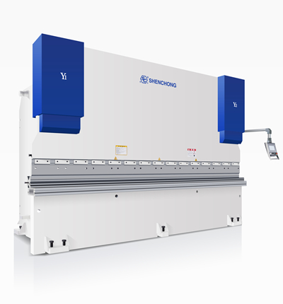
A CNC sheet bending machine is a sheet metal machine that uses the relative movement between an upper and lower die to apply pressure to a thin metal sheet, causing plastic deformation and forming a sheet metal with a specified angle and size.
Compared to ordinary mechanical bending machines, modern CNC sheet metal bending machines mainly achieve high precision, repeatability, and automated processing through:
CNC system + servo drive + back gauge system + hydraulic/electric servo drive + die system + safety protection system.
Drawing input → Bending program creation → Material/thickness setting → Die selection → Bending sequence calculation → Back gauge positioning → Trial bending → Angle correction → Mass production
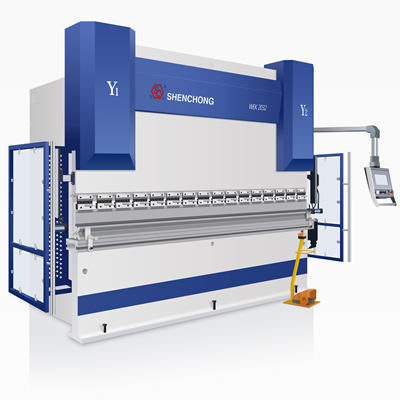
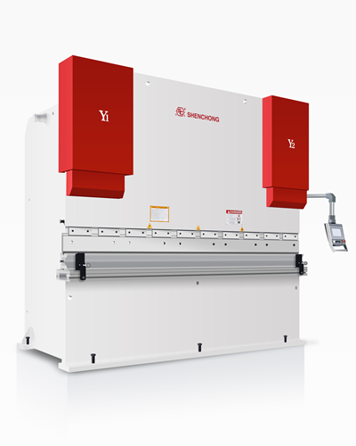
A typical CNC sheet bending machine mainly consists of the following parts:
Includes:
- Left and right side plates
- Worktable
- Upper crossbeam
- Base
- Hydraulic cylinder mounting structure
- Connecting beam
The frame is responsible for bearing the huge load generated during the bending process.
The upper crossbeam mounts the upper die and moves up and down via a hydraulic cylinder or servo drive mechanism.
Main function:
To drive the upper die to complete the downward movement, bending, pressure holding, and return stroke.
The worktable mounts the lower die.
Some high-end equipment configurations:
- Hydraulic clamping
- Automatic clamping
- Mechanical clamping
- Deflection compensation system
- CNC mechanical compensation
- Hydraulic compensation
The back gauge is an important component of CNC sheet bending machines to ensure bending dimensions.
Axis | Main Functions |
X-axis | Back gauge forward and backward movement |
R-axis | Gutter up and down movement |
Z1/Z2 | Independent left and right stop finger movement |
X1/X2 | Multi-axis forward and backward positioning |
Delta X | Special structure auxiliary positioning |
Different devices may use different combinations.
One of the core components of a modern bending machine is the CNC control system.
ESA, Delem, Cybelec, EL series
S630, S640, S650, EL15T, EL19T, DA53T, DA58T, DA66T, DA69T
2D/3D programming → Automatic calculation of bending sequence → Die collision check → Back gauge control → Angle compensation → Bending simulation → Program saving → Production data management.
For example:
Modern systems can now input workpieces through a graphical interface and calculate the processing procedure based on material, thickness, die, and bending parameters.
This is the most important part of the entire operation manual.
The most dangerous areas of a bending machine are mainly concentrated in:
The clamping area formed by the upper die, lower die, workpiece, and related moving parts.
ISO 6909:2026, released in 2026, specifically addresses the safety of bending machines, clearly defining aspects such as mechanical hazards, protective devices, control systems, operating modes, non-mechanical hazards, and instructions for use.
Therefore:
Before operation:
- Wear work clothes
- Wear safety shoes
- Wear protective glasses if necessary
- Long hair must be secured
- No loose jewelry
- No clothing that could easily get caught in the equipment
- Familiarize themselves with the location of the emergency stop button
- Familiarize themselves with the location of the safety light curtain
- Familiarize themselves with the foot switch
- Familiarize themselves with the hazardous areas of the equipment
❌ Do not put your hands between the upper and lower dies
Even when the equipment is stopped, do not put your hands in the hazardous area.
❌ Do not directly check the bending angle with your hands
Measurements should be taken only after the equipment has been stopped in a safe position.
❌ Do not adjust the dies while the equipment is running
Must:
Stop the equipment → Disconnect the relevant power supply → Confirm safety → Then make adjustments.
❌ Do not remove safety protection devices
Including:
- Safety light curtains
- Rear guards
- Side guards
- Safety relays
- Emergency stop devices
- Interlocking devices
Safety protection devices are not "accessories that affect efficiency," but rather an integral part of the equipment's safety system.
An inspection should be performed before the first use of the CNC sheet bending machine each day.
It is recommended to use the "10-Point Pre-Start Inspection Method":
Confirm:
- No obvious mechanical damage
- No abnormal deformation
- - No obvious oil leakage
No loose parts
Check:
- Hydraulic oil level
- Oil pipes
- Connections
- Valve assemblies
- Cylinders
- Check for oil leaks
If obvious oil leakage is found, production must stop.
Confirm:
- Automatic lubrication system is normal
- Sufficient lubricating oil
- No abnormal dry friction on guide rails
Check:
- Electrical cabinet
- Power supply
- Fan
- Grounding
- Cables
- Plugs
- Control system
After pressing the emergency stop button, confirm that the equipment can enter a safe state.
Confirm:
Light curtain blocking → Dangerous movements should stop/prohibit starting according to the safety logic designed in the equipment design.
Production must not be carried out when the safety device is malfunctioning.
Confirmation:
Ascend, Descend, Stop, Emergency Stop/Safety Function
All normal.
Confirmation:
- Die installation correct.
- Die no cracks.
- Die no obvious damage.
- Upper and lower die centers basically aligned.
- Die locking reliable.
Confirmation
- X-axis normal
- R-axis normal
- Z-axis normal
Guide finger movement no interference.
Confirmation:
- Worktable free of debris.
- No tools near the die.
- No personnel in the backgauge area.
- No obstacles around the equipment.
Recommended Standard Procedure:
Main Power → Control Power → CNC System → Hydraulic/Servo System → Return to Reference Point → Check Alarms → Manual Test → Automatic Production
Turn on: Main Power Switch
Observe the electrical control cabinet and system status.
Wait for the system to complete initialization.
Do not frequently operate the buttons before the system has finished starting.
Based on the equipment structure:
Start the hydraulic pump/servo drive system.
Observe:
- Oil pressure
- Temperature
- Motor sound
- Pump sound
- Alarm information
After starting the CNC sheet bending machine, the following is usually required:
Zeroing / Return to Reference Point
The main purpose is to establish:
The correspondence between the machine position and the CNC coordinates.
For example:
X-axis zeroing
R-axis zeroing
Z1/Z2 zeroing
Other auxiliary axes zeroing
Note:
During the return to reference point process, do not extend your body into the moving area.
The die is one of the core factors affecting bending quality.
Confirm:
- Upper die length
- Die type
- Die height
- Tip status
- Clamping method
When using a quick-clamping system, confirm that the die is fully locked.
Select the V-groove according to the plate thickness and bending method.
Common Relationships:
V-groove Width V ≈ 6t~8t
Where:
t = Sheet Thickness
However, the actual V-groove selection must consider:
- Material
- Sheet Thickness
- Bending Radius
- Bending Length
- Maximum Pressure
- Workpiece Structure
- Manufacturer's Die List
It cannot be selected based on a single fixed multiple.
For thin sheet processing, special attention is usually paid to:
V-groove too small:
- Required pressure increases
- Easily damages material
- Increases die load
V-groove too large:
- Increases bending radius
- Possibly decreases positioning stability
- Increases difficulty in controlling bending angle
For thin sheets: The upper die radius (R-angle) cannot simply be pursued to be as small as possible.
Too small may lead to:
- Material indentation
- Surface damage
- Local stress concentration
- Die wear
Modern CNC systems generally employ two main methods.
Input:
- Material
- Thickness
- Length
- Bending Angle
- Bending Position
- Die
The system automatically generates the machining steps.
Step-by-step input:
- X-axis position
- Y-axis position
- Bending angle
- Back gauge position
- Bending speed
- Holding time
- Return position
Suitable for:
- Simple workpieces
- Modifying old programs
- Special processes
At least the following must be confirmed when creating the program:
- Material
- Plate thickness
- Plate length
- Tensile strength
- Bending angle
- Bending radius
- Upper die/lower die
- V-groove width
Common materials:
- Q235
- Q345
- SPCC
- GI
- 304 stainless steel
- 316 stainless steel
- Aluminum plate
- Galvanized plate
Standard production flow:
Step 1: Confirm drawing.
↓
Step 2: Confirm material.
↓
Step 3: Confirm plate thickness.
↓
Step 4: Select upper and lower dies.
↓
Step 5: Create CNC program.
↓
Step 6
Check bending sequence.
↓
Step 7
Check for mold collision.
↓
Step 8
Start back gauge.
↓
Step 9
Return to reference point.
↓
Step 10
Single-step trial run.
↓
Step 11
Place sheet metal.
↓
Step 12
Back gauge positioning.
↓
Step 13
Depress the foot pedal.
↓
Step 14
Complete the first bend.
↓
Step 15
Measure the angle.
↓
Step 16
Measure the dimensions.
↓
Step 17
Adjust parameters.
↓
Step 18
Mass production.
This is a crucial step in the production process.
Do not begin mass production immediately after program setup.
The first piece must undergo:
"Trial bending → Measurement → Correction → Another trial bending"
Check at least:
- Bending angle
- Bending length
- Hole position
- Edge distance
- Parallelism
- Perpendicularity
- Surface indentation
- Workpiece deformation
For example:
Target 90°
Actual measurement 90.8°
This indicates an angle deviation, requiring angle compensation according to the equipment control system.
Generally:
- Actual angle too large → Increase bending amount
- Actual angle too small → Reduce bending amount
However, different controllers may have different parameter definitions.
Therefore, do not mechanically assume that "the Y value must be added/subtracted by a certain amount," but must be adjusted according to the coordinate definition of the corresponding system.
Springback is frequently encountered in thin sheet bending.
After bending, the material will experience a certain degree of elastic recovery.
For example:
Program: 90°
After bending: 92°
This is a typical springback phenomenon.
Influencing factors include:
- Material strength
- Plate thickness
- Bending radius
- V-groove width
- Bending method
- Bending length
- Material batch
- Rolling direction
Although thin plates require less bending force, this does not mean the processing is simple.
Key concerns:
Consider:
- Using a suitable V-groove
- Using a protective film
- Selecting an appropriate die
- Reducing unnecessary die pressure concentration
Long and thin workpieces are prone to:
- Sagging
- Warping
- Twisting
- Unstable positioning
Using: Bending follow-up support device
Especially suitable for:
- Long plates
- Thin plates
- Large workpieces
- Stainless steel plates
- Aluminum plates
The back gauge is an important mechanism to ensure bending dimensions.
During production, it is essential to ensure that the plate reliably abuts the back gauge finger.
Do not:
- Forcefully bump the stop finger
- Strike the back gauge forcefully
- Put your hand into the dangerous area of the back gauge
- Manually intervene during the back gauge's movement
For: 4+1 axis, 6+1 axis, 8+1 axis
Equipment operators must understand:
More axes ≠ More manual adjustments required.
The core value of a multi-axis system is:
- Automatic positioning
- Multi-point positioning
- Complex workpiece positioning
- Reduced manual adjustments
- Improved repeatability
For example:
X + R + Z1 + Z2 allows for more flexible back gauge positioning.
Complex workpieces are usually not simply bent "from left to right".
The program needs to consider:
- Workpiece dimensions
- Bending direction
- Die length
- Workpiece interference
- Back gauge interference
- Upper die interference
- Formed edge interference
- Operator handling space
Modern CNC systems can use graphic simulation and collision checks to assist in determining the bending sequence.
After the first piece is confirmed to be qualified:
Pre-production record:
- Program number
- Material
- Plate thickness
- Die
- Bending angle
- First piece size
Then enter the automatic cycle.
During mass production:
Operators need to conduct regular spot checks.
At least the following should be checked per batch:
- Angle
- Dimensions
- Appearance
- Bending position
- Surface quality
If continuous deviations occur, stop production immediately.
Do not "take chances" through continuous production.
Normal Shutdown Procedure:
① Finish the current workpiece
Do not shut down the equipment directly while the workpiece is stuck in the mold.
② Return the upper crossbeam to a safe position
Ensure the equipment is in a safe state.
③ Exit automatic cycle
Stop automatic operation.
④ Save program
Confirm the program has been saved.
⑤ Shut down the hydraulic/servo system
Execute according to equipment requirements.
⑥ Shut down the CNC system
Wait for the system to shut down normally.
⑦ Shut down the main power
Finally, turn off the main power.
Stop the CNC sheet bending machine immediately in the following situations:
- Personnel enter the danger zone
- Workpiece is severely stuck
- Mold malfunction
- Abnormal equipment noise
- Severe hydraulic system leak
- Smoke from the electrical system
- Abnormal upper crossbeam movement
- Back gauge malfunction
- Safety light curtain malfunction
- Serious control system failure
Immediately: Press the emergency stop button
Then: Evacuate personnel from the danger zone → Cut off relevant power → Determine the fault → Notify maintenance personnel.
Check:
- Main power supply
- Emergency stop button
- Safety light curtain
- Foot switch
- Safety relay
- CNC alarm
- Hydraulic system
- Servo drive
Key checks:
- Safety light curtain
- Emergency stop
- Foot switch
- Safety circuit
- CNC alarm
- Hydraulic pressure
- Y-axis drive system
Possible causes:
- Material thickness variation
- Material strength variation
- Springback variation
- Die wear
- V-groove inconsistency
- Y-axis calibration problem
- Incorrect deflection compensation parameters
- Sheet metal positioning problem
The true performance of a CNC sheet bending machine depends not only on the machine's tonnage and CNC system, but also on:
Correct die selection + Correct programming + Correct positioning + Correct operation + First piece inspection + Parameter compensation + Standardized maintenance + Safety management.
The standard operator workflow is as follows:
Power-on check → Zeroing → Die check → Program selection → Parameter check → Back gauge check → Plate placement → First piece bending → Dimensional inspection → Parameter correction → Batch production → Spot check → Cleaning → Shutdown
For thin sheet metal processing, the following should be given special attention:
Bending angle stability, repeatability, material springback, surface protection, minimum folding edge size, die selection, and consistency in continuous production.
Related information:
TOP 8 CNC Plate Bending Machine Manufacturers in Asia
Top 15 Plate Bending Machine Manufacturers in the World
5 Keys to Choose CNC Bending Machine for Sheet Metal
Analysis: Bending Springback of Sheet Metal Parts
Complete Solutions of Press Brake Bending Problems | FAQ