
Press brakes are widely used and highly valuable machines. Many industries from aerospace, to furniture, automotive, electrical and power, food industry, industrial industry, and more use press brakes.
Press brakes are machine pressing tools for bending sheet and plate materials, usually sheet metal. The press brake forms predetermined bends by clamping the workpiece between a matching punch and die.
Many different angles and shapes can be molded using press brakes. Simple or complex designs can be achieved with the aid of press brake machines. Some press brakes for sale are hand operated and others are computerized, called CNC press brakes, and there are various types of press brakes from hydraulic to electrical.
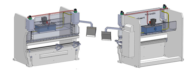
A press brake consists of two C-Frames that form the sides of the machine. On the bottom, they are connected by a large table, and on the top, by a moveable upper beam. It is possible to see the opposite configuration in a press brake.
The bottom tool rests on the table, while the top tool attaches to the upper beam.
A press brake is usually long and narrow, so that larger pieces of sheet metal can be bent using the machine. Press brakes bend sheet metal by lowering a punch onto the sheet metal that has been sat on top of a die in the correct position. Press brakes can bend the metal several times.
Press brake structure is comprised of many different components. Each component serves a specific function in achieving the desired results of bending that a press brake offers.
A press brake has three basic parts, the ram or top tool, the bottom tool, and the mechanism that drives the ram. The main operation of all press brakes is the same, however, how the ram is used to exert force and shape the part can differ on different types of press brakes.
Some press brakes have hydraulic or electrical systems that move the ram and form the desired shapes and curvatures. Some press brakes are hand operated through a crank and shaft. All these different types all perform the same basic function of bending and shaping materials, mostly sheet metal.
– Machine Frame
The frame holds the machine together and supports the other parts of the press brake. Usually, this is two C-Frames that make the sides of the machine. The frame keeps the press brake together and working.
Large press brakes are incased in a bigger frame and are not always C-shaped. Many of them have a square shape. The frame of the press brake is welded by the left and right upright plates, or side frames, a worktable, often called a bed and vertical moving ram.
– Ram Mechanism
Press brakes can have upper and lower rams, both, or just one. Both rams are the driving or resisting parts of the press brake machine. Usually made from large, strong steel plates, the rams can be assisted by internal hydraulic cylinders to resist crowning.
The ram of mechanical press brakes is moved vertically and driven by a crank mechanism. The crank is powered by the flywheel.
Pneumatic press brakes use air pressure to move the ram. On hydraulic press brakes, the ram is moved by two synchronized hydraulic cylinders.
The ram is the driving mechanism that exerts or resists the force of the press brake.
If you want to learn more about CNC press brake axis, you can read this article: How to Choose CNC Press Brake Axis?
– Back Gauge
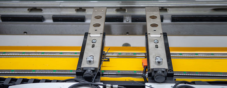
The back gauge is a mechanical system attached to a CNC press brake. The main function of a back gauge is to interact with the press brake computer numerical control, or CNC, and to move along many different axes.
The back gauge precisely positions metal pieces to be formed. Most back gauges can move in six different axes of movement. A separate electric motor guides and controls each individual axes. Most times, a back gauge is sold along with a press brake.
For modern automated CNC machines, the back gauge is a stop for the workpiece. The back gauge centers the desired bend line over the ‘V’ opening of the die.
– Punch and Die
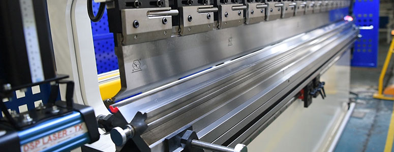
The punch is the top tool, and the die is the bottom tool. They work together at the processing end of a press brake. The punch and die fold the workpiece between a matching punch and die and apply force to bend the material into the predetermined shape.
There are many different die types and each of them is used for different forming jobs. The types of dies generally used are:
90 degree dies, acute angle dies, beading dies, box-forming dies, channel-forming dies, corrugating dies, curling dies, four-way die blocks, gooseneck dies, hemming dies, multiple-bend dies, radius dies, rocker-type dies, rotary bending dies, seaming dies, tube, and pipe forming dies, u-bend dies, and V-dies.
– Hydraulic System
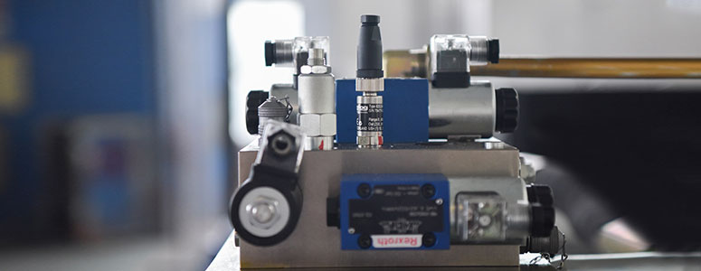
The hydraulic system is comprised of five main areas.
The powerplant is the hydraulic pump. The mechanical energy input by the prime mover is converted into the pressure energy of the liquid. The system uses this as an energy supply.
The actuator is the hydraulic cylinder or motor. The fluid pressure energy is converted into mechanical energy to perform the work on the load.
The control device is various hydraulic control valves. The valves are used to control the direction, flow, and pressure of the fluid to keep the actuator in-line to complete the desired work tasks.
The assisting equipment is the fuel tank, oil filter, pressure gauge, cooler, water separator, oil mister, muffler, pipe fittings, pipe joints, and other signal converters. These create the needed parameters for proper operation.
The working medium is the hydraulic oil or compressed air to transfer motion and power.
– Electrical System

There are two main types of electric press brake systems. A screw-type and a belt-and-pulley. In the screw type, an electric motor screws the brake down. This is similar to a traditional hydraulic system.
In the belt-and-pulley system, the motor drives a belt that is connected to a series of pulleys which forces the brake down.