+86-158-9507-5134
info@shenchong.com
 EN
EN
The following systematically analyzes how to improve the shearing accuracy of a guillotine plate shear machine (hydraulic shearing machine) from multiple dimensions, including mechanical structure, hydraulic system, blades, back gauge, worktable, frame rigidity, plate positioning, parameter settings, operation methods, testing methods, maintenance, and automation control.
Many people believe that the accuracy of a shearing machine is simply "whether the cut dimensions are accurate," but this is not comprehensive.
The comprehensive accuracy of a guillotine plate shearing machine mainly includes:
Accuracy Items | Main Performance Indicators |
Shearing Length Accuracy | Error between actual cutting length and set dimension |
Shearing Angle Accuracy | Angle error between the cutting line and the reference edge of the board |
Diagonal Accuracy | Whether the four sides and two diagonals of the rectangular board are consistent |
Parallelism | Whether the two sides are parallel after cutting |
Straightness | Whether the cutting edge is bent or wavy |
Perpendicularity | Whether the cutting edge is close to 90° with the reference edge |
Repeatability | Whether the same dimension is consistent when cutting multiple times |
Sectional Quality | Burnt, collapsed corners, tears, deformation, etc. |
Sheet Deformation | Whether the board is twisted or warped after cutting |
Long-Term Stability | Whether the accuracy decreases significantly after continuous work |
Therefore, improving the precision of a guillotine shearing machine cannot be achieved solely by adjusting the back gauge.
The truly effective method should be:
Equipment rigidity + blade condition + blade gap + shearing angle + back gauge + hydraulic stability + sheet positioning + standardized operation + regular inspection = comprehensive shearing precision.
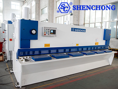
When a guillotine shearing machine cuts thick plates, it generates very large shearing forces.
For example:
4×2500mm
8×3200mm
12×3200mm
16×4000mm
20×4000mm
25×2500mm
As the plate thickness increases, the shearing force increases rapidly.
If the frame rigidity is insufficient, the following may occur during the shearing process:
- Upper blade holder deformation
- Worktable deformation
- Side plates opening
- Blade holder position changes
- Blade gap changes
- Inconsistent shearing states at the left and right ends
The final result is: The set dimensions may be accurate, but the actual cut plate material is inaccurate.
High-quality hydraulic guillotine shearing machines typically adopt:
Integral steel plate welded frame → Stress relief → Precision machining.
Instead of simple assembly.
Key locations include:
- Left and right side panels
- Worktable
- Upper tool holder
- Rear support
- Hydraulic cylinder mounting area
- Tool holder guide rail area
Sufficient structural strength is essential.
Large welded frames generate significant welding stress.
Without proper stress relief, the following may occur after long-term operation:
- Slight deformation of the frame
- Changes in tool holder position
- Changes in worktable flatness
- Decrease in guide rail accuracy
Therefore:
Welding completion ≠ The frame has reached its final precision.
Proper stress relief and finishing are still required.
Shenchong high-precision shearing machine adopts an all-steel welded structure. The wall panels, worktable, and tool holder body are all subjected to secondary tempering to relieve stress. Vibration is used to relieve stress at welded areas, giving the frame excellent rigidity and stability. Therefore, you don't need to worry. The shearing straightness reaches ±0.03mm/m.
Many shearing machines exhibit "inaccurate dimensions," which is actually not a problem with the back gauge, but rather with the blades.
When blades wear down:
- Increased shearing resistance
- Easier to tear the sheet
- Increased burrs
- Deformation of the sheared edge
- Easier displacement of the sheet
- Ultimately leading to dimensional errors
The sheared surface typically has:
- A noticeable bright band
- A relatively uniform fracture area
- Smaller burrs
- A relatively straight sheared edge
Possible consequences:
- Increased burrs
- Rough surface
- Tearing
- Local bending
- Sheet deformation
- Abnormal shearing noise
Therefore, regular blade inspection is crucial.
Even if the blade itself is of high quality, inaccurate installation will affect shearing accuracy.
Key areas to check:
- Straightness of the blade
- Blade mounting plane
- Blade clamping tightness
- Parallelism of the upper and lower blades
- Blade height consistency
- Bolt tightness
Especially after replacing the blade, the relevant precision should be rechecked.
This is one of the most important factors in improving the precision of a shearing machine.
Blade clearance refers to the optimal distance between the upper and lower blades.
Different plate thicknesses, materials, and tensile strengths require different optimal blade clearances.
If the blade clearance is too large:
The plate is easily squeezed.
Increased burrs.
Rough cross-section.
The plate is prone to deformation.
Decreased dimensional stability during shearing.
Tearing may occur at the sheared edge.
If the blade clearance is too small:
Shearing force increases significantly.
The blades are easily damaged.
Increased load on the hydraulic system.
The plate is prone to secondary compression.
Increased equipment vibration.
Therefore: A smaller blade clearance is not always better. It must be adjusted appropriately based on the material and thickness.
For example:
Ordinary carbon steel is generally easier to shear.
Stainless steel, due to its higher strength and better toughness, usually requires blade clearance adjustments based on its material properties.
Aluminum sheets are relatively soft, and the blade gap setting needs to consider:
- Material thickness
- Material toughness
- Surface quality requirements
Therefore, it is not possible to simply use "one set of blade gaps" to cut all materials.
One of the most important parameters of a guillotine plate shear is the shearing angle.
The shearing angle affects:
- Shearing force
- Sheet deformation
- Sheared cross-section
- Sheet twisting
- Shearing stability
May lead to:
- Decreased unit shearing force
- Increased sheet deformation
Sheet twisting is more likely (especially noticeable with thin sheets)
May lead to:
- Increased shearing force
- Increased hydraulic system load
- Difficulty shearing thick sheets
- Increased blade stress
Therefore, the shearing angle should be adjusted appropriately according to the equipment design range and sheet thickness.
For example, shearing:
1mm, 1.5mm, 2mm, 3mm thin sheets
If the parameters are not appropriate, the following can easily occur:
- Sheet warping
- Sheet twisting
- Cryo-cut edges
- Dimensional instability
Therefore, thin sheet processing cannot be simply operated according to the parameters for thick sheets.
The backgauge is the core component determining the accuracy of length dimensions.
Typical structure includes:
- Backgauge crossbeam
- Lead screw
- Guide rail
- Servo motor
- Reduction mechanism
- Stop finger
- CNC control system
Focus on checking:
- Lead screw wear
- Nut clearance
- Lubrication status
- Axial clearance
- Mechanical jamming
If there is significant clearance in the lead screw, the following will occur:
The set value is 1000mm, but the actual value may be 999.5mm.
Even different errors will occur when moving in different directions.
The guide rail needs to be:
- Parallel
- Clean
- Lubricated
- No significant wear
- No jamming
If the guide rail resistance is inconsistent, the backgauge may:
The left side arrives first, and the right side arrives later.
Ultimately causing the sheet metal positioning to be tilted.
The stop finger is the direct contact point for sheet metal positioning.
If:
- The stop fingers are loose
- The stop fingers are deformed
- The left and right stop fingers are at different heights
- The stop fingers are not installed perpendicularly
All of these will affect dimensional accuracy.
Modern CNC guillotine plate shearing machines typically use:
CNC + servo motor + precision lead screw/ball screw + linear guide rails
forming a closed-loop or high-precision positioning system.
Advantages include:
- High positioning speed
- High repeatability
- Continuous processing of multiple dimensions
- Automatic compensation
- Convenient program recall
Many users easily overlook the workbench.
In fact, the sheet metal is positioned and sheared on the workbench.
If the workbench:
is dented
is warped
has localized wear
has a large amount of metal filings
has welding slag
has burrs
the sheet metal may not adhere stably.
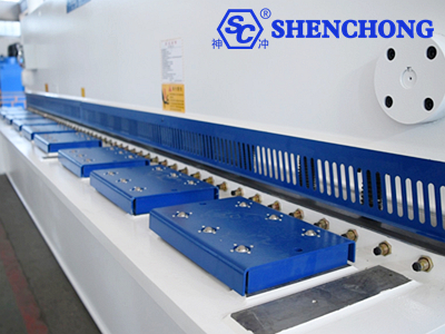
Pay special attention to:
metal filings + scale + burrs + oil stains
These may seem insignificant, but they can cause localized positioning errors of 0.2–1 mm or even larger on the sheet metal.
Therefore, the workbench and the material-holding area should be cleaned after each shift.
Hydraulic guillotine plate shears typically have a pressure device.
The function of the pressure device is to:
hold the sheet metal in place during the shearing process, preventing it from moving.
Insufficient clamping force:
The sheet will move.
The shearing dimensions will change.
The sheet will vibrate easily.
The sheared edges will be unstable.
Excessive clamping force is also bad.
If the clamping force is too high:
Indentations may be left on the sheet surface.
Thin sheets are prone to deformation.
The surface quality of the material will deteriorate.
Therefore, the clamping system should achieve: Stable clamping of the sheet without causing significant deformation.
The hydraulic system directly affects:
- Shearing speed
- Shearing pressure
- Tool holder movement
- Material clamping action
- Return stability
If the hydraulic system pressure fluctuates significantly, it may cause inconsistent shearing behavior.
Inspect:
- Oil level
- Oil cleanliness
- Oil color
- Oil temperature
- Oil contamination status
Filter clogging may cause:
- Decreased system flow
- Slow operation
- Pressure fluctuations
- Increased temperature rise
Therefore, it should be inspected and replaced according to the equipment maintenance cycle.
Key Inspection:
- Solenoid valve
- Proportional valve
- Relief valve
- Throttle valve
- Check valve
If the valve body movement is unstable, it may affect the consistency of tool holder movement.
This is a very important factor for large hydraulic guillotine plate shearing machines.
If the left and right hydraulic cylinders move asynchronously, the following may occur:
The positions of the left and right blade holders may differ.
This ultimately leads to:
Different blade clearances on the left and right sides
Different shearing qualities on the left and right sides
Non-parallel sheared edges
Angle errors in the sheet metal.
The following checks can be performed:
- Run the blade holder slowly.
- Check the positions of both sides.
- Check if the up-and-down movement of the blade holder is consistent.
- Check the blade clearances on the left and right sides.
- Check for differences in the sheared cross-section on the left and right sides.
If: Burrs are obvious on the left, but normal on the right.
Or: The shearing dimensions on the left are stable, but the dimensions on the right vary.
Then the left-right synchronization and blade holder system should be the primary focus of inspection.
Not all errors can be attributed to the machine.
The sheet material itself also significantly affects shearing accuracy.
For example:
- Uneven sheet thickness
- Sheet warping
- Internal stress in the sheet
- Crooked edges
- Uneven surface
- Inherent dimensional errors in the sheet
Especially for:
- Laser-cut sheets
- Plasma-cut sheets
- Hot-rolled sheets
- Cold-rolled sheets
- High-strength steel
There may be some internal stress.
Stress release after shearing may cause:
Sudden bending or twisting of the sheet material.
This does not necessarily indicate poor shearing machine accuracy.
When positioning the sheet material, the operator must ensure:
Sheet material reference edge → close to the stop → maintain stability → then proceed with shearing.
The following conditions must be avoided:
- Sheet material suspended in mid-air
- Sheet material placed at an angle
- Sheet material not firmly against the guide finger
- One side firmly against the guide finger, the other side tilted upwards
For rectangular sheets, side guides + back guides can be used to form a stable two-dimensional positioning reference.
This improves:
- Length accuracy
- Width accuracy
- Right angle
- Diagonal accuracy
Especially important when shearing large sheets.
For example: 2500×1250mm
Or: 4000×2000mm
If the sheet material protrudes too much from the worktable, its own weight will cause it to sag.
The results are:
- Changes in sheet positioning
- Sheet movement during shearing
- Errors at the shearing edge
- Adding front/rear support
For large sheets, the following can be configured:
- Front support
- Rear support
- Pneumatic support
- Automatic support
- Roller worktable
- Conveying system
The purpose is to:
Reduce the impact of the sheet's weight on positioning accuracy.
The accuracy of modern CNC shearing machines also depends on the parameters of their control system.
Key parameters include:
- Back gauge zero point
- Axial parameters
- Electronic gear ratio
- Servo parameters
- Encoder feedback
- Software compensation
- Limit positions
Back gauge requires "actual size calibration".
This is a very effective method to improve accuracy on-site.
For example:
Setting: 1000mm
Actual measurement: 999.2mm
This indicates an error of 0.8mm.
This cannot be simply attributed to "mechanical inaccuracy." Instead, the following should be checked:
- Zero point
- Lead screw
- Transmission mechanism
- Encoder
- Parameter ratio
- Mechanical backlash
Then recalibrate.
Mechanical backlash is a major enemy of accuracy.
Key Inspection Points:
- Screw Nut
- Gears
- Couplings
- Bearings
- Guide Rails
- Stop Connectors
- Tool Holder Connections
Especially the back gauge: Different measurement results for forward and reverse movement are a typical mechanical backlash signal.
Shearing speed also affects shearing stability.
For thin plates, excessive speed may lead to:
- Plate vibration
- Instant positioning
- Changes in cross-sectional quality
For thick plates, excessive speed may lead to:
- Increased shearing impact
- Increased hydraulic system load
- Equipment vibration
Therefore, appropriate shearing parameters should be selected based on the material and thickness.
For multi-sized plates, it is not recommended to rely entirely on manual operation.
A reasonable schedule should be arranged according to the processing drawings.
For example:
Process the same material, the same thickness, and similar dimensions together as much as possible.
Advantages:
- Reduced parameter modifications
- Reduced tool gap adjustments
- Reduced operational errors
- Improved repeatability
- Improved production efficiency
This is crucial for improving equipment accuracy and lifespan.
For example, if the equipment is rated at 12×3200mm, do not use it as 15×3200mm for an extended period.
Over-specification machining can easily cause:
- Frame deformation
- Blade damage
- Hydraulic system overload
- Back gauge vibration
- Decreased accuracy
It is recommended to establish an equipment precision testing system.
At least the following should be tested:
For example:
100mm
500mm
1000mm
1500mm
2000mm
Test each individually.
For example, set to 1000mm. Position continuously 10 times.
Record:
1000.1
999.9
1000.0
1000.1
999.9…
Observe the error range.
Measure the distance between the two sides after shearing a long plate.
For rectangular plates: Measure the two diagonals.
If:
D1 ≠ D2, it indicates an angular or positioning error.
The precision of the shearing machine is dynamically changing.
The equipment may be highly accurate upon initial installation, but after several months of use:
Lead screw wear, guide rail contamination, blade wear, loose bolts, hydraulic oil contamination, and bearing wear will all lead to decreased accuracy.
It is recommended to establish a three-tiered maintenance system:
Worktable, Blade, Back gauge, Hydraulic oil level, Leakage, Abnormal noise, Bolts
Guide rail lubrication, Lead screw lubrication, Back gauge clearance, Blade condition, Material clamping system
Frame accuracy, Tool holder parallelism, Tool clearance, Hydraulic system, Back gauge positioning accuracy, Left and right cylinder synchronization, Electrical system, CNC parameters
Even the best equipment will struggle to maintain high precision if operated improperly.
Operators must master:
- Confirm Material: Material type, thickness, and length.
- Confirm Tool Clearance: Adjust according to material and thickness.
- Confirm Backgauge: Check the actual position of the backgauge.
- Confirm Shearing Angle: Confirm according to processing requirements and equipment parameters.
- Confirm Finished Product: The first piece must be inspected.
In batch processing, do not immediately begin continuous production after the first piece.
Correct Process:
Program Input → Parameter Confirmation → First-Piece Shearing → Dimensional Inspection → Adjustment → Continue Batch Production.
This avoids:
Machine parameter errors → Continuous processing of 100 pieces → 100 pieces scrapped.
The following standard workflow can be established:
Drawing Confirmation
↓
Material Confirmation
↓
Plate Thickness Inspection
↓
Shearing Parameter Setting
↓
Blade Clearance Inspection
↓
Backgauge Calibration
↓
Workbench Cleaning
↓
Plate Positioning
↓
Material Pressing
↓
First Piece Shearing
↓
Dimension Inspection
↓
Parameter Correction
↓
Batch Production
↓
Sampling Inspection
↓
Equipment Cleaning and Maintenance
Phenomena | Priority Inspection |
Length is all too large/too small | Back gauge calibration |
Accurate in the forward direction, inaccurate in the reverse direction | Mechanical clearance |
Different dimensions on the left and right sides | Back gauge parallelism |
Different burrs on the left and right cutting edges | Knife gap, tool holder, synchronization |
Severe burrs on the board | Blade, knife gap |
Severe twisting of the board | Shearing angle, knife gap, material |
Shearing deformation of thin boards | Shearing angle, clamping, knife gap |
Different dimensions at both ends of long boards | Back gauge parallelism |
Inconsistent diagonals | Positioning, side stop, back gauge |
Crooked shearing edges | Blade, frame, tool holder |
Gradually changing dimensions during continuous processing | Thermal stability, hydraulic, mechanical wear |
Incomplete shearing of thick boards | Blade, knife gap, hydraulic pressure, out-of-specification |
Abnormal shearing sound | Knife gap, blade, hydraulic system |
To truly improve accuracy, the priorities should be as follows:
Recommend proceeding in the following order, rather than immediately modifying CNC parameters.
Frame → Tool Post → Worktable → Guide Rail
Inserts → Insert Installation → Clearance → Shearing Angle
Backgauge → Lead Screw → Guide Rail → Servo → Encoder
Pressure → Flow Rate → Oil → Valve Assembly → Cylinder Synchronization
Sheet Metal Quality → Positioning → Pressing → Supporting → Operating Methods
CNC Parameters → Axis Compensation → Zero Point → Repeat Positioning → Data Recording
For companies with high precision requirements, the following configuration can be used:
CNC system + servo backgauge + precision ball screw + linear guide + encoder feedback.
This significantly improves:
- Positioning speed
- Positioning accuracy
- Repeatability
- Multi-size machining capability
- Automatic level
Especially valuable for mass production.
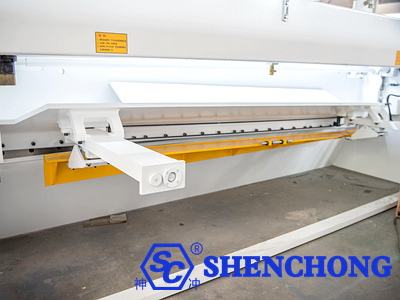
For: Long plates, thick plates, and large-size plates
The following configurations can be used:
- Automatic front material handling
- Automatic backgauge
- Pneumatic material handling
- Roller material handling
- Servo material handling
Its core value is not simply "convenient loading and unloading," but rather:
Reducing the impact of the plate's weight on positioning and shearing accuracy.
For a modern sheet metal factory, the following system can be further established:
Shearing Machine → CNC → MES → Production Database
Records:
- Equipment Number
- Material
- Thickness
- Gap
- Shearing Angle
- Backgauge Position
- Actual Dimension
- Operator
- Processing Time
- Equipment Status
- Precision Inspection Result
This creates a closed-loop management system:
"Equipment Precision Data → Production Data → Maintenance Data"
If condensed into the 15 most practical measures for on-site use, they are:
- Improve the overall rigidity of the frame
- Ensure the machining accuracy of the worktable
- Keep the blades sharp
- Install the blades correctly
- Adjust the blade gap according to the material
- Set the shearing angle appropriately
- Ensure the synchronization of the left and right hydraulic cylinders
- Ensure the parallelism of the back gauge
- Eliminate the lead screw and transmission backlash
- Calibrate the CNC back gauge
- Ensure the stability of the pressing system
- Reduce the suspension of large plates
- Use a material support device
- Strictly implement first-piece inspection
- Establish a regular accuracy inspection and maintenance system
Among these, the most noteworthy are:
Blade gap + Blade + Back gauge + Frame rigidity + Hydraulic cylinder synchronization + Plate positioning
These six factors are usually the core links affecting the actual shearing accuracy of hydraulic guillotine shearing machines.
If the goal is to upgrade the guillotine plate shearing machine from a basic production level to a high-precision, mass-production, and stable production level, then the following should be further considered:
CNC back gauge + servo positioning + precision lead screw/guide rail + automatic material handling + rapid tool gap adjustment + digitized precision detection + preventative maintenance