+86-158-9507-5134
[email protected]
 EN


Sheet metal horizontal grooving machines are important forming auxiliary equipment in modern precision sheet metal processing. They are mainly used to process V-grooves on the surface of metal sheets such as stainless steel, carbon steel, aluminum, and copper, creating conditions for subsequent precision bending, decorative forming, and the manufacture of complex sheet metal structures.
Compared with traditional direct bending processes, properly slotted metal sheets can achieve smaller inner bend radii, clearer bend edges, and, under certain conditions, reduce the bending force, thus improving the appearance quality of decorative sheet metal products.
This article systematically introduces the correct operation of horizontal v groove machines for metal sheets, covering aspects such as equipment structure, working principle, technical parameters, operation procedures, slotting process, CNC system settings, tool selection, safety regulations, maintenance, common faults, and processing quality control.
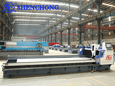
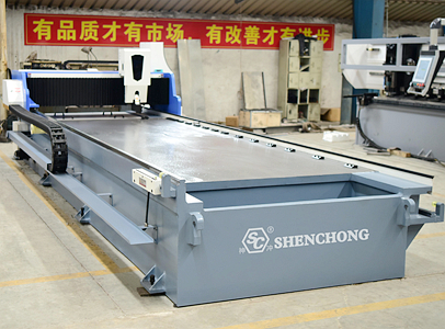
Horizontal CNC grooving machines typically employ a horizontal worktable structure. The sheet metal is laid flat on the worktable, and the workpiece is fixed by a hydraulic or pneumatic clamping mechanism. A CNC system controls the tool holder to perform linear planing along a set trajectory, gradually machining V-grooves with specified depths, angles, and positions.
Processing Materials | Processing Characteristics | Typical Applications |
304/316 Stainless Steel | High strength, significant work hardening | Elevator decoration, curtain walls, door frames |
Q235 Carbon Steel | Good machinability | Enclosures and cabinets, steel structure decoration |
5052 Aluminum Alloy | Relatively soft texture, prone to tool sticking | Aluminum curtain walls, decorative panels |
Copper Plate | Good ductility, easily forms burrs | Architectural decoration, handicrafts |
Galvanized Steel Plate | Caution required to prevent plating damage | Ventilation equipment, metal casings |
- Landslide-mounted sheet metal is suitable for processing large-format sheets.
- CNC positioning improves the consistency of batch slotting.
- Multiple shallow cuts help control slot depth and surface quality.
- Multiple parallel slots and slots with different spacings can be processed.
- Suitable for use with CNC press brake bending machines to achieve precision sheet metal forming.
- Highly valuable for stainless steel decorative panels, door panels, and architectural metal components.
Note that slotting reduces the effective cross-sectional thickness of the sheet metal. Therefore, it's not enough to simply pursue deep slots and small bending radii; workpiece strength and safety must also be considered.
Main Components | Functional Description |
Machine Frame | Supports the entire machine, ensuring rigidity and stability |
Horizontal Table | Bears the sheet metal, providing a machining reference |
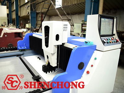
CNC System | Manages slot positions, slot depths, machining speeds, and programs |
Tool Post Assembly | Installes the grooving tool to complete the planing motion |
Servo Drive System | Controls the movement of the tool holder and positioning mechanism |
Material Holding Device | Fixes the sheet metal, reducing machining vibration |
Rear Positioning Mechanism | Controls the sheet metal position and slot spacing |
Lubrication System | Reduces wear on moving parts |
Hydraulic or Pneumatic System | Provides power to actuators such as the material clamping mechanism |
Electrical Control System | Controls equipment operation, interlocks, and provides fault alarms |
Equipment from different manufacturers may vary significantly in terms of tool holder drive, material clamping method, number of axes, positioning accuracy, and control logic. The instruction manual for the specific model should be consulted during operation.
The core processing principle of a sheet metal horizontal grooving machines is: by using a tool to perform multiple straight cuts along the surface of the sheet metal, material is gradually removed, ultimately forming a V-shaped groove of specified geometric dimensions.
Material Placement and Positioning
↓
Material Holding Mechanism Fixes the Plate
↓
CNC System Executes the Machining Program
↓
Cutting Tool Planes Layer by Layer to Form a V-groove
↓
Measure Groove Depth, Width, and Position
↓
Inspection Passes, Transfers to Bending Process
Assumptions:
t: Original plate thickness, in mm
d: Groove depth, in mm
s: Remaining plate thickness at the bottom of the groove, in mm
Then: s = t - d
For example, when the plate thickness is 2.0 mm and the groove depth is 1.2 mm:
s = 2.0 - 1.2 = 0.8 mm
In this case, the remaining plate thickness at the bottom of the groove is 0.8 mm.
This result only reflects the geometric dimensions and does not represent that the remaining strength meets the requirements. The actual allowable groove depth needs to be determined by combining material properties, bending angle, load, fatigue requirements, and process verification.
The following procedure applies to common CNC horizontal V-grooving machines. Specific button names, zeroing sequence, axis movement direction, and interlocking logic must be based on the equipment manufacturer's operating manual.
Operators should complete the following checks.
Start-up Checklist:
- Confirm power supply, cables, grounding, and electrical cabinet are in normal condition.
- Check emergency stop button, safety protection devices, and interlocking functions.
- Check hydraulic oil level, air pressure, and for leaks.
- Check for damaged, loose, or abnormally worn cutting tools.
- Clean chips from the worktable, positioning blocks, and material clamping area.
- Check guide rails, lead screws, and lubrication system.
- Verify plate dimensions, thickness, material, and machining drawings.
- Confirm there are no personnel or obstacles within the equipment's movement range.
Connect the main power and control power according to the equipment manual.
Start the CNC system and wait for the self-test to complete.
Check for servo, hydraulic, pneumatic, or limit alarms.
Return each axis to the reference point according to the equipment specifications.
Confirm that the tool holder, positioning mechanism, and clamping device are in a safe condition.
Perform a no-load run or low-speed test run under safe conditions to confirm that the direction of movement is normal.
Some CNC grooving machines use X, Y, and Z axes to control tool holder movement, groove positioning, and cutting depth; other models use different axis definitions. The equipment manufacturer's operating manual also emphasizes that homing and preparation for machining are crucial steps in the startup process.
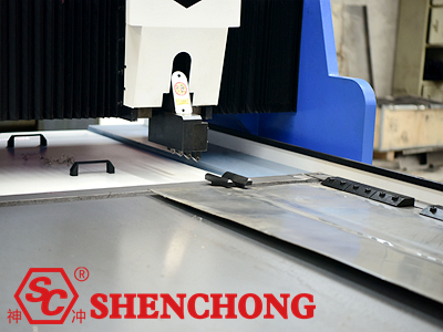
Place the sheet metal stably on the worktable. Determine the reference edge, groove line position, and machining direction according to the machining drawings.
Operating Requirements:
The contact surface between the sheet metal and the worktable should be clean to avoid warping caused by chips.
The reference edge of the sheet metal should reliably contact the positioning device.
Do not forcibly flatten severely deformed sheet metal beyond the equipment's allowable range.
Use the clamping mechanism to clamp the workpiece, ensuring there is no risk of slippage.
For decorative panels such as mirror stainless steel, appropriate surface protection measures should be used to prevent indentations and scratches.
Enter the CNC system's programming interface and input the sheet material length, width, thickness, groove position, groove depth, tool parameters, and machining cycle.
Parameters | Explanation |
Sheet Length | Actual workpiece length |
Sheet Width | Actual workpiece width |
Sheet Thickness | Measured thickness (not just nominal value) |
Grooving Position | Gutter centerline or system-defined positioning coordinates |
Grooving Depth | Target total depth of cut |
Grooving Angle | Determined by tool and process requirements |
Single Cut Depth | Depth of material removed in each machining pass |
Processing Speed | Set according to material, tool, and equipment capabilities |
Number of Processes | Number of cutting passes required to achieve the target groove depth |
Grooving should generally not be done in one cut to the final depth, but rather using multiple layers of planing.
For example: For a 2mm thick stainless steel plate, with a planned total groove depth of 1.0mm, the following sample plan can be used:
Cutting passes | Current cutting depth | Cumulative groove depth |
First pass | 0.40mm | 0.40mm |
Second pass | 0.30mm | 0.70mm |
Third pass | 0.20mm | 0.90mm |
Fourth pass | 0.10mm | 1.00mm |
The above is an example demonstrating layered logic and is not a universally recommended cutting depth. Actual cutting depths should be adjusted based on material hardness, insert grade, tool holder rigidity, clamping conditions, and the manufacturer's allowed depth of cut.
Before formal mass production, it is recommended to perform a first piece verification.
Check the slot positions, tools, and depth of cut in the program.
Perform a no-load run with the tool safely retracted to check for collision risks.
Machin the first piece using verified, conservative parameters.
Observe the chip morphology, cutting sound, and workpiece clamping status.
After machining is complete and the tool is confirmed to have stopped and retracted to a safe position, measure the slot depth, slot spacing, and slot shape.
Adjust parameters if necessary and perform another trial run.
It is strictly forbidden to clean chips, measure slot depth, or adjust the material by hand while the tool is in operation.
After the first piece passes inspection, the verified machining program can be used for mass production.
During machining, focus on observing tool wear, slot depth changes, material positioning, cutting sound, and the status of the clamping mechanism. In case of abnormal vibration, tool breakage, workpiece movement, or alarm, immediately stop processing according to equipment specifications and investigate the cause.
Wait for the tool holder to completely stop and return to a safe position.
Remove the sheet metal after releasing the clamp.
Inspect the grooving quality according to the drawings and record the results.
Shut down the control and power systems according to the equipment shutdown procedure.
After the equipment has safely stopped, use appropriate tools to clean up the chips.
Complete the daily equipment inspection and handover records.
During long-term operation, CNC sheet metal horizontal grooving machines may experience problems such as inconsistent grooving depth, groove position deviation, tool breakage, rough groove bottom, equipment vibration, abnormal material clamping, servo alarms, and hydraulic system malfunctions. These faults not only affect grooving accuracy and processing efficiency but may also cause tool damage, sheet metal scrap, and even equipment safety accidents.
The following section analyzes common faults, their causes, troubleshooting methods, and solutions from seven aspects: processing quality, tooling system, mechanical transmission, CNC servo, hydraulic pressure, electrical system, and equipment maintenance.
Fault Symptoms | Main causes | Troubleshooting |
Inconsistent grooving depth | Sheet warping, uneven worktable, tool wear | Check the table, clamping device, and tool compensation |
Grooving position deviation | Loose positioning stop, incorrect coordinate settings | Calibrate the positioning mechanism and program |
Inaccurate V-groove angle | Incorrect blade angle, misaligned tool installation | Check tool specifications and installation |
Rough groove bottom surface | Tool wear, vibration, improper cutting parameters | Replace the inserts and optimize machining parameters |
Burns appearing during grooving | Dull blade, tool sticking, poor chip removal | Replace the inserts and improve chip removal |
Tool chipping | Excessive depth of cut, tool collision, excessively hard material | Reduce depth of cut and check the tools |
Vibration during grooving | Loose tool holder, worn guide rail, insufficient clamping | Check the transmission and clamping system |
Movement during sheet metal processing | Insufficient clamping pressure, poor sheet positioning | Check the clamping mechanism |
Tool holder movement not smooth | Insufficient guide rail lubrication, abnormal lead screw, obstruction by foreign objects | Check the lubrication and transmission mechanism |
CNC system unable to return to zero | Abnormal origin switch, servo malfunction | Check sensors and drive alarms. Troubleshoot based on alarm codes |
Servo motor alarm | Overload, abnormal encoder, drive malfunction | Check the hydraulic system |
Insufficient hydraulic pressure | Low oil level, pump malfunction, hydraulic leakage | Check the actuator |
Material clamping device malfunction | Abnormal solenoid valve, pneumatic or hydraulic system | Check positioning and transmission accuracy |
Poor dimensional repeatability | Mechanical clearance, unstable clamping | Check alarms and safety circuits |
Sudden equipment stoppage | Safety interlock, overload, abnormal power supply | Check the table, clamping device, and tool compensation |
Symptoms:
The same V-groove may exhibit uneven depths, with the front being deeper than the back, or multiple grooves showing inconsistent actual depths. In severe cases, this can cause instability in bending angles and appearance.
Main Causes:
The sheet metal thickness itself may be inconsistent.
The sheet metal may be warped, not fully conforming to the worktable.
The worktable may have chips, burrs, or localized wear.
The clamping force of the blank holder mechanism may be uneven.
The cutting tool may be worn or the tool compensation setting may be incorrect.
There may be clearance in the tool holder guide mechanism.
Excessive cutting load may cause elastic deformation of the tool holder.
Solutions:
Measure the actual thickness of the sheet metal at different locations.
Clean the contact surfaces between the worktable and the sheet metal.
Check if the blank holder mechanism can reliably hold the workpiece.
Check the tool wear and tool compensation value.
Use a depth measuring tool to detect variations in groove depth.
If a regular error persists, a professional should check the flatness of the worktable, the accuracy of the tool holder guide, and related mechanical clearances.
Preventive Measures:
Perform first-piece inspection before processing each batch of materials and regularly check the repeatability of groove depth.
Symptoms:
The actual groove position does not match the drawing, or there is a deviation in the spacing between multiple parallel grooves.
Possible causes include loose positioning blocks, non-straight sheet metal reference edges, incorrect program coordinates, servo positioning deviation, and transmission mechanism clearance.
During troubleshooting, first confirm the program dimensions and positioning reference, then measure the actual groove position. If all grooves show deviations in the same direction, prioritize checking the workpiece reference and coordinate offset. If the deviation gradually increases with the movement distance, check the transmission, calibration, and feedback system of the positioning axis.
Do not arbitrarily modify servo parameters to mask errors before identifying mechanical or program causes.
Main Causes:
The actual tool angle does not match the program requirements.
Incorrect insert installation angle.
Weared or chipped tool tip.
Chip present on the tool holder positioning surface.
Vibration or displacement of the tool holder during cutting.
Solution:
Verify the insert specifications, inspect the tool holder mounting surface, and measure the machined groove shape. After replacing the insert, re-verify tool compensation and first-piece quality.
Note that the V-groove tool angle and the final bending angle are not necessarily the same; bending process and material springback must also be considered.
Symptoms:
Obvious scratches, periodic tool marks, tear marks, or localized unevenness appear on the groove bottom.
The main causes are usually tool wear, unsuitable cutting parameters, insufficient workpiece clamping, guide rail vibration, or secondary scratches from chips.
It is recommended to first check the clamping condition between the tool edge and the workpiece, and then verify the cutting speed and depth of cut item by item. For stainless steel, special attention should be paid to work hardening and tool friction.
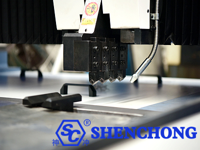
The causes of burrs are not entirely the same for different materials.
Materials | Common Problems | Areas for Improvement |
304 Stainless Steel | Work hardening, burrs, tool wear | Maintain tool sharpness and perform proper layered cutting |
316 Stainless Steel | High cutting resistance, tool wear | Select suitable inserts and control cutting load |
Aluminum Alloy | Tool sticking, built-up edge | Use tools and chip removal systems suitable for aluminum |
Q235 Carbon Steel | Cutting burrs, tool marks | Optimize tool condition and cutting parameters |
Copper Plate | Burrs caused by material ductility | Use sharp tools and improve chip control |
Common causes include excessive depth of cut, incompatible tool grade, unstable workpiece clamping, loose tool holder, and accidental tool impact.
If chipping occurs, stop machining immediately. After complete cessation of movement and necessary energy isolation, inspect the insert, tool holder, and workpiece. Do not simply replace the insert and resume the original machining program; first, eliminate the cause of the chipping.
Possible causes include inappropriate tool material selection, excessive cutting load, high material hardness, poor chip removal, or abnormal friction.
It is recommended to maintain a tool life record, tracking the machining length, insert replacement frequency, and groove surface quality for each material to determine a reasonable tool change cycle.
First, check the tool type, tip position, tool holder contact surface, fastening condition, and tool compensation value. First-piece verification is mandatory after replacing inserts or tool holders.
Possible causes:
Weared or insufficiently lubricated guide rail sliders.
Malfunction of the lead screw, bearing, or coupling.
Loose tool holder connection components.
Inappropriate tool extension.
Cutting load exceeds the allowable range of the equipment or tool.
When troubleshooting, first determine if the abnormal noise only occurs during cutting. If it is normal during no-load operation but abnormal during cutting, prioritize checking the cutting load, tool, and workpiece clamping. If the abnormal noise is present even during no-load operation, focus on checking the mechanical transmission mechanism.
Check the guide rail lubrication, lead screw condition, mechanical obstruction, and servo alarm. If jamming is found, do not attempt to move the tool holder by increasing the motor torque limit or forcing jogging.
Multiple positioning tests at the same coordinates can be used to determine if the error is repeatable.
If the error direction is random, focus on checking clamping, transmission clearance, and feedback abnormalities. If the error varies with the running distance, check the transmission calibration and mechanical accuracy.
Faults | Possible causes | Inspection Direction |
Insufficient clamping force | Low hydraulic pressure, leakage, abnormal pressure regulation | Check oil level, pressure, and piping |
Slow clamping action | Oil contamination, valve malfunction, insufficient flow | Check hydraulic valves and filtration system |
Unsynchronized clamping | Actuator blockage, control malfunction | Check the operation of each pressing mechanism |
Excessive hydraulic pump noise | Insufficient oil level, air intake, pump wear | Check oil suction conditions and pump status |
Abnormally high oil temperature | Poor heat dissipation, continuous high load | Check cooling and hydraulic system |
Oil cylinder leakage | Aging seals, loose connections | Check seals and piping |
Hydraulic system maintenance must be performed by qualified personnel. Before disassembling pipelines, power should be isolated, stored pressure released, and safety confirmed as required. High-pressure hydraulic leaks must not be located by hand.
Check main power supply, control power supply, emergency stop status, and equipment alarm information. If internal electrical cabinet testing is involved, it should be performed by qualified electrical personnel.
Possible causes include origin sensor malfunction, abnormal limit signal, mechanical obstruction, encoder malfunction, and incorrect zeroing parameters.
Troubleshooting should be performed item by item according to the CNC system alarm information and the machine tool manual. Zeroing should not be achieved by shorting safety signals or forcibly modifying coordinates.
Alarm Types | Common Causes | Troubleshooting Directions |
Servo Overload | Mechanical jamming, excessive cutting load | Check transmission resistance and machining load |
Excessive Following Error | Motion obstruction, control malfunction | Check mechanical and feedback systems |
Encoder Alarm | Encoder or connection wiring malfunction | Check encoders and cables |
Overvoltage | Power supply or braking system malfunction | Inspect by electrical personnel |
Overcurrent | Motor, drive, or mechanical malfunction | Diagnose using alarm codes |
Communication Failure | Communication line, interface, or controller malfunction | Check connections and system status |
Alarm codes for servo drives from different brands have different meanings; please refer to the corresponding drive manual for accurate interpretation.
Identify processing abnormality or equipment alarm
↓
Safely stop the equipment and record the fault phenomenon
↓
Confirm alarm code, program, and workpiece status
↓
Inspect the cutting tool, clamping, positioning, and mechanical systems
↓
If necessary, have a professional inspect the electrical, hydraulic, and servo systems
↓
Troubleshoot and restore protection and safety interlocks
↓
No-load test → First piece inspection → Resume production
Sheet metal horizontal grooving machines pose risks such as tool cutting, metal chip splashing, material clamping injuries, sharp edge cuts on the sheet, and collisions with moving mechanisms.
Requirements to be observed during operation:
The equipment should be operated by trained and authorized personnel.
Check emergency stop, safety interlocks, and protective devices before operation.
Use appropriate cut-resistant gloves when loading and unloading materials; do not wear loose gloves that may be caught when near moving tools.
Wear safety goggles and other protective equipment required by the risk assessment while working.
It is strictly forbidden to put hands into the dangerous areas of the cutting tools, clamping devices, and moving mechanisms.
It is strictly forbidden to adjust the position of the sheet metal while processing is in progress.
Processing speed must not be increased by shielding interlocks or removing protective covers.
If abnormal noise, vibration, workpiece slippage, or tool breakage occurs, processing must be stopped immediately.
Energy isolation procedures such as locking and tagging must be performed before maintenance, tool replacement, and clearing of dangerous areas.
Workpieces exceeding their permissible dimensions, thickness, and material range must not be processed using the equipment.
These requirements are also consistent with the safety operating recommendations published by the grooving machine manufacturer.
- Ensure reliable sheet metal positioning: Select a stable positioning reference to prevent cumulative positional errors during multi-groove processing.
- Control the remaining sheet thickness at the bottom of the groove: For thin sheets and decorative parts, groove depth deviations can significantly affect the angle and appearance after bending.
- Maintain stable tool condition: Establish a tool usage record and replace tools promptly based on wear condition.
- Employ reasonable multi-pass cutting: For deep grooves or difficult-to-machine materials, rationally allocate the depth of cut for each pass to avoid excessive load on the final cut.
- Implement first-piece inspection: Re-verify the machining results after each change of material, tool, or program.
- Establish standardized machining programs for materials and thicknesses of the same type.
- Optimize the machining sequence according to groove position and tool configuration to reduce unnecessary idle strokes.
- Use validated program templates for recurring orders.
- Employ appropriate auxiliary loading and unloading devices to reduce manual handling time.
- Schedule the grooving process in conjunction with subsequent bending processes.
- Record tool life, machining time, and defect rate to continuously optimize the process.
Grooving Process: By locally thinning the sheet metal, a predetermined bending line is formed.
Bending Forming: Achieves smaller inner corner radii and clearer surface edges.
In high-end decorative sheet metal manufacturing, horizontal v grooving machines and CNC press brake bending machines can form a precision forming process chain:
Sheet Metal Blanking
↓
Horizontal CNC Slotting
↓
Slot Depth and Position Inspection
↓
CNC Bending Forming
↓
Dimensional and Appearance Inspection
This process is particularly suitable for products such as elevator car decorative panels, building curtain walls, stainless steel door frames, display cabinets, and hotel metal decorative parts.
However, for load-bearing components, fatigue load components, and safety-critical components, strength calculations and process verification should be performed first, and deep slotting should not directly replace conventional bending.
- Complete equipment safety and mechanical condition checks before starting the machine.
- Accurately measure the sheet metal thickness and confirm that the material is within the processing range.
- Ensure reliable sheet metal positioning and clamping.
- Select appropriate blades and groove shapes based on the material.
- Set the groove depth appropriately, retaining sufficient remaining plate thickness to meet design requirements.
- Utilize a proven layered cutting scheme.
- First-piece inspection must be completed before batch processing.
- Continuously monitor tool wear and cutting status during processing.
- Strictly adhere to safe operation and equipment maintenance procedures.
- Evaluate grooving accuracy in conjunction with subsequent bending quality.
Conclusion:
The key to using a sheet metal horizontal grooving machines lies not only in correctly setting the CNC program, but also in the coordinated operation of plate positioning, groove depth control, tool management, layered cutting, and safe operation. Only by establishing standardized operation and quality inspection processes can we consistently produce workpieces with accurate groove positions, uniform groove bottoms, and good surface quality, providing reliable conditions for subsequent high-precision bending.