+86-158-9507-5134
[email protected]
 EN


A 3-roller sheet rolling machine is an important piece of equipment in the field of metal sheet forming and processing. It mainly uses the relative motion between three rollers, rotational friction, and plastic bending deformation to process flat metal sheets into cylindrical, arc-shaped, conical, and other curved workpieces.
Three-roll plate rolling machines are widely used in industries such as pressure vessels, petrochemicals, steel structures, wind power equipment, shipbuilding, pipeline engineering, environmental protection equipment, and construction machinery.
This article provides a systematic analysis of the equipment's structure, working principle, processing flow, mechanical analysis, rolling accuracy, operating techniques, common defects, maintenance, and equipment selection.
A 3-roller plate bending machine typically consists of a frame, upper roll, lower roll or side roll, transmission device, hydraulic system, electrical control system, bearing support mechanism, and unloading device.
Components | Main Functions |
Upper work roll | Apply bending pressure to sheet metal; some models also function as a drive unit |
Lower work roll | Support sheet metal, provide driving force, or participate in position adjustment |
Side work roll | Participate in bending and pre-bending in asymmetrical or horizontally adjustable structures |
Frame | Bear rolling loads and ensure overall equipment rigidity |
Main drive system | Drive the work rollers to rotate and complete sheet metal feeding |
Hydraulic system | Control roller shaft lifting, lateral movement, and unloading mechanisms |
Reduction gear mechanism | Reduce rotational speed and increase output torque |
Electrical control system | Control roller shaft position, running speed, and operating sequence |
Tilting bearing housing | On applicable models, open the roller end supports for easy removal of the cylinder |
Safety protection device | Implement emergency stop, limit switches, interlocks, and other safety protections |
The two lower rollers are usually fixed, while the upper roller moves up and down, forming a symmetrical three-point bending structure. This structure is simple and low-cost, but pre-bending at both ends of the plate is usually difficult.
The three rollers are arranged asymmetrically, and bending of the plate is achieved by adjusting the side rollers. Compared to the traditional symmetrical structure, some models can more easily perform end pre-bending.
This machine typically changes the support spacing and bending conditions by adjusting the horizontal position of the lower rollers and the vertical movement of the upper roller. It is suitable for processing medium-thick plates, thick plates, and large cylinders. The actual movement depends on the equipment design.
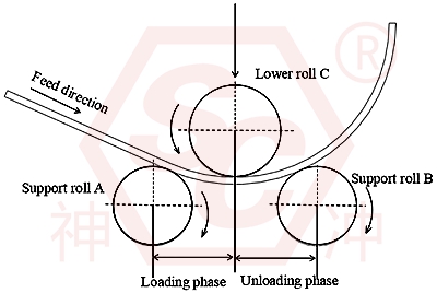
The core principle of a three-roller plate bending machine is: using the bending torque generated by the three working rollers to cause the metal plate to exceed the material's elastic limit, resulting in continuous plastic bending deformation and ultimately forming the desired curvature.
The following uses a common symmetrical three-roll plate bending machine as an example.
During processing:
Two lower rollers provide support for the metal sheet.
The upper roller applies a downward bending load.
The work roller rotates, propelling the sheet continuously through friction.
The sheet undergoes elastoplastic deformation under bending moment.
Adjusting the pressure of the upper roller changes the final curvature of the sheet.
Through repeated rolling, the target diameter is gradually formed.
For other three-roll structures, the specific roles of the pressure roller, support roller, and drive roller may differ, but the basic principle of plastic bending remains the same.
When a metal sheet is bent, different stress and strain states occur along its thickness:
- The outer material is stretched, creating tensile stress.
- The inner material is compressed, creating compressive stress.
- A neutral layer exists in the middle with longitudinal strain close to zero.
- When the local stress exceeds the material's yield point, the sheet undergoes plastic deformation.
- The plastic deformation retained after unloading keeps the sheet in its curved shape.
It is important to note that the material will exhibit a certain degree of elastic rebound after unloading, therefore the loading curvature during processing usually needs to be greater than the final required curvature.
For an ideal circular arc:
κ = 1/R
Where:
κ: Sheet curvature
R: Bending radius near the neutral layer of the sheet
When the sheet thickness is t, and the bending radius is much larger than the thickness, the surface bending strain can be approximated as:
ε ≈ t/2R
For example, if the sheet thickness is 10 mm and the bending radius is 500 mm:
ε ≈ 10/(2*500) = 1%
This means that the geometric bending strain on the outer surface of the sheet is approximately 1%. This calculation is for understanding the degree of deformation and is not equal to the actual rolling force required by the equipment.
The standard cylindrical rolling process typically includes the following stages:
Process Flow: From Flat Plate to Formed Cylinder
- Sheet Material Preparation
- Positioning and Centering
- End Pre-bending
- Initial Rolling
- Multiple Finish Rolling
- Unloading and Inspection
Before rolling, the material, thickness, width, length, and surface condition of the sheet material need to be confirmed.
Key Inspection Points:
- Check for defects such as cracks, delamination, and severe corrosion.
- Check if the sheet material thickness is within the equipment's allowable range.
- Check for burrs on the cut edges of the sheet material.
- Check if the sheet material length meets the cylinder circumference and subsequent welding process requirements.
- Check if the sheet material's yield strength meets the equipment's rolling capacity.
Place the sheet material between the work rolls, ensuring the sheet material edges are parallel to the roll shafts.
If the sheet material is tilted, it may cause:
- Inconsistent diameters at both ends of the cylinder.
- Tapering of the workpiece.
- Deviation of the sheet material to one side.
- Uneven localized deformation. - Subsequent welding alignment is difficult.
Therefore, proper alignment is a crucial prerequisite for improving rolling accuracy.
Pre-bending is a critical step in three-roll plate rolling.
Because of the geometric distance between the work rolls, some structures cannot generate sufficient bending moment before the plate ends enter the effective bending zone, leaving relatively straight ends. This phenomenon is commonly referred to as straight edges or residual straight edges.
The purpose of pre-bending is to minimize the length of straight edges, forming an arc shape at both ends of the plate that approximates the curvature of the target cylinder.
Different equipment handles this differently:
Mechanical symmetrical type: Usually requires an additional pre-bending process or auxiliary measures.
Asymmetrical type: Some models can achieve end pre-bending using the side roll positions.
Hydraulic horizontal adjustment type: Pre-bending can be completed through combinations of roll positions.
It cannot be assumed that all 3-roller sheet rolling machines have the same pre-bending capacity; the actual capacity should be determined based on the equipment structure and the residual straight edge specifications provided by the manufacturer.
After pre-bending, formal rolling begins.
- Adjust the position of the work rollers and set the initial bending amount.
- Start the main drive system to drive the sheet metal forward.
- The sheet metal continuously passes through the bending area between the rollers.
- Gradually increase the bending amount according to the sheet metal thickness, material strength, and target diameter.
- After the initial rolling, measure the curvature and diameter.
For thick plates, a multi-stage loading method is usually used to avoid excessive pressure at once, which could lead to equipment overload, slippage, or workpiece defects.
After the initial rolling, the cylinder may have problems such as uneven curvature, asymmetry at both ends, or excessive ellipticity.
At this time, corrections can be made based on the measurement results:
- Adjust the roller position.
- Perform appropriate reciprocating rolling.
- Check the diameter at both ends of the cylinder.
- Correct local curvature differences.
- Evaluate material springback.
- Confirm the alignment condition before welding.
Note that fine rolling is not an unlimited repetition of rolling. Over-correction may cause localized over-bending, surface indentation, or unnecessary work hardening.
Once the workpiece meets the process requirements:
- Stop roller rotation.
- Release the pressure from the work rollers according to the prescribed procedure.
- Support the workpiece using appropriate support devices.
- For equipment with a tipping mechanism, open the corresponding bearing housing.
- Remove the cylinder according to the equipment operating procedures.
- Inspect the finished product's dimensions, roundness, surface quality, and end fit.
For large or heavy cylinders, reliable lifting and anti-rollover measures must be implemented in advance.
The processing capacity of a 3-roller plate bending machine depends not only on the maximum plate thickness, but also on the material strength, plate width, target diameter, roller dimensions, and pre-bending requirements.
Parameters | Impact on processing |
Maximum coil thickness | Determines the ability to roll thick plates under specific conditions |
Maximum coil width | Determines the axial length of workpieces that can be processed |
Upper roll diameter | Affects equipment rigidity, bending capacity, and minimum forming diameter |
Lower roll diameter | Affects plate support, contact conditions, and driving capability |
Lower roll center distance | Affects bending moment, bending force, and equipment stress state; higher strength generally requires a larger bending moment |
Material yield strength | Determines the minimum achievable cylinder size |
Minimum coil diameter | Affects production efficiency and operation control |
Coil speed | Affects end straight edges and subsequent alignment quality |
Pre-bending capacity | Affects the consistency of axial curvature during wide plate rolling |
Roller deflection | Determines the ability to roll thick plates under specific conditions |
In the ideal three-point bending model, if the distance between the two support points is S, and a concentrated force F is applied at the center, then the maximum bending moment is:
Mmax = ( F·S) / 4
The load in an actual three-roll plate bending machine is a complex contact bending problem, affected by factors such as roller size, plate curvature, contact position, friction, and material hardening. Therefore, this formula cannot be directly used to determine the tonnage of the equipment.
For a rectangular cross-section, using an ideal elastoplastic material model, the fully plastic bending moment can be approximately expressed as:
MP = (σybt2)/4
Where:
σy: material yield strength
b: plate width
t: plate thickness
This model shows that, under similar conditions, the required plastic bending moment is approximately proportional to the square of the plate thickness.
For example, increasing from 10 mm to 20 mm, under ideal conditions, the required plastic bending moment increases to approximately four times, not twice.
The greater the thickness, the higher the required bending moment; the greater the yield strength of the material, the higher the load required to produce plastic deformation.
For example, the rolling force of ordinary carbon steel and high-strength steel of the same thickness may differ significantly. Therefore, the ability of the equipment to process the plate cannot be judged solely based on the plate thickness.
When rolling wide plates, the work rolls may exhibit elastic deflection, resulting in inconsistent curvature along the width of the plate.
Common effects include:
- Difference in curvature between the middle and ends.
- Decreased straightness of the cylinder generatrix.
- Increased local gap during alignment.
Solutions include appropriately selecting the roller diameter, adopting suitable deflection compensation structures, and controlling the actual processing load.
Material springback is affected by the following factors:
- Material elastic modulus
- Yield strength
- Work hardening characteristics
- Plate thickness
- Target bending radius
- Actual loaded curvature
In actual production, the appropriate overbending amount should be determined through trial rolling, measurement, and process parameter correction, rather than using a fixed compensation value for all materials.
If the plate is tilted when entering the work rolls, it may form a conical or spiral deformation. The feed on both sides of the plate needs to be continuously observed during the rolling process.
The parallelism between the work rolls directly affects the bending uniformity of the plate in the width direction.
During equipment installation, maintenance, and commissioning, the roller parallelism, bearing condition, and frame accuracy should be checked according to the manufacturer's requirements.
Comparison Items | 3-roll sheet bending machine | 4-roll sheet bending machine |
Number of Working Rollers | 3 units | 4 units |
Structural Complexity | Generally lower price, varies depending on the model | Typically higher quality |
Sheet Clamping | Depends on the specific roll system structure | Typically can be clamped by upper and lower rolls |
End Pre-bending | Some models require auxiliary processing | Typically easier to integrate with pre-bending |
Automation Capability | Can be automated | Typically easier to integrate with automated processes |
Operational Difficulty | Related to the model and control system | More advanced automatic control configurations |
Equipment Cost | Generally lower price for the same level | Typically higher quality for its class |
Applicable Scenarios | Useful for rolling round plates and large cylinders, etc | Batch rolling, high efficiency and automated production |
It should be noted that advanced three-roll variable geometry plate rolling machines can also process large, thick plate workpieces and possess high pre-bending capabilities and automation levels. Therefore, it cannot be simply assumed that four-roll machines are superior to three-roll machines in all performance aspects.
From the perspective of production management and process optimization, the following aspects can be focused on:
Standardize plate preparation, pre-bending, initial rolling, finish rolling, and unloading to reduce unnecessary repetitive adjustments.
Record the roller positions and correction experience corresponding to different materials, plate thicknesses, widths, and target diameters.
Use appropriate feeding platforms, centering devices, or auxiliary material support systems to reduce repeated manual corrections.
Determine a reasonable single adjustment amount based on material strength and target curvature to avoid repeated bending and reversals.
For equipment with corresponding functions, PLC or CNC systems can be used to manage roller positions, speeds, and process formulas.
For large-diameter, thin-walled, or heavy-duty cylinders, appropriate side supports, top supports, and discharge devices can be used to improve forming stability.
Regularly inspect the hydraulic system, transmission system, roller surface condition, bearings, and safety devices to reduce equipment failures and downtime.
When purchasing a 3-roller sheet rolling machine, do not only compare the "maximum plate thickness" and "maximum plate width."
It is recommended to provide the manufacturer with the following process information:
Selection Items | Content to be confirmed |
Material Type | Q235, Q355, 304 stainless steel or other materials |
Material Strength | Yield strength, tensile strength, etc. |
Sheet Thickness | Common and maximum thickness |
Sheet Width | Actual machining width |
Target Diameter | Minimum inner diameter and common cylinder diameter |
Pre-bending Requirements | Whether end pre-bending is required and the allowable straight edge length |
Processing Shape | Cylinder, arc, conical cylinder or other curved surface |
Production Scale | Single piece, small batch or batch production |
Automation Requirements | Whether CNC, material handling, and loading/unloading systems are required |
Finished Product Precision | Roundness, diameter, straightness and alignment requirements |
It is particularly important to confirm with the manufacturer whether the equipment's maximum rolling thickness, maximum pre-bending thickness, and minimum rolling diameter can be simultaneously met under the specified plate width and material strength conditions. These parameters usually cannot be simply added together independently.
3-roller sheet rolling machines are equipment with significant risks of extrusion, entanglement, and heavy object movement.
Special attention should be paid during operation:
- Operators must receive equipment training and be familiar with emergency stop, limit switch, and safety interlock functions.
- Hands, gloves, or tools must not be placed into the working roll clamps.
- Do not directly support the plate material entering the roll system with your hands during rolling.
- When rolling large cylinders, use support and lifting equipment that meets the load requirements.
- Do not exceed the manufacturer's specified range for plate thickness, plate width, material strength, and minimum rolling diameter.
- Before unloading, ensure the workpiece is reliably supported and operate the tipping mechanism in the prescribed sequence.
- Before maintaining, cleaning jammed materials, and replacing parts, perform applicable energy isolation and locking procedures.
In terms of maintenance, key checks should focus on lubrication, hydraulic oil condition, seals, transmission mechanism, roller surfaces, fasteners, and electrical safety protection systems.
The essence of three-roll plate rolling machines is to utilize the bending moment generated by the work rollers to induce controllable plastic deformation of the metal sheet, achieving the desired curvature through continuous feeding and roller position adjustment.
From a technical perspective, the five most important aspects are:
- Correct Equipment Structure Selection: Selecting the appropriate three-roll configuration based on the material, plate thickness, width, and target diameter.
- Controlling Plate End Pre-Bending: Minimizing straight edges to improve subsequent jointing quality.
- Reasonable Bending Amount Control: Avoiding excessive load at once, balancing processing efficiency and equipment safety.
- Considering Material Springback: Improving cylinder dimensional accuracy through measurement and process correction.
- Perfect Rolling and Finished Product Inspection: Controlling roundness, taper, surface quality, and dimensional consistency before welding.
For modern sheet metal processing enterprises, the 3-roller sheet rolling machine is not only a basic forming equipment, but can also be combined with CNC systems, hydraulic control, automatic feeding, auxiliary support and intelligent production management systems to form a more efficient sheet metal rolling processing solution.