+86-158-9507-5134
[email protected]
 EN


This analysis comprehensively examines CNC press bending process from the perspectives of precision, efficiency, quality, technology, equipment, and automation. CNC press brake bending is a crucial process in modern sheet metal manufacturing, widely used in industries such as chassis and cabinets, electrical equipment, automotive parts, elevators, construction machinery, building curtain walls, stainless steel products, and metal structural components.
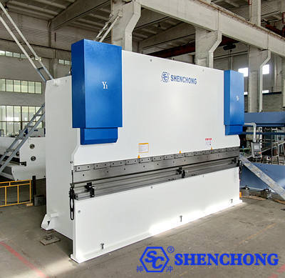
As the manufacturing industry moves towards higher precision, higher efficiency, flexibility, and intelligence, traditional bending methods relying on operational experience are no longer sufficient to meet the production demands of complex sheet metal products. Improving CNC bending processing is not only about increasing bending speed, but more importantly, about achieving synergistic optimization of bending accuracy, product consistency, production efficiency, material utilization, and overall manufacturing costs.
CNC bending process is a comprehensive manufacturing process involving equipment, materials, molds, programs, operation, and inspection.
Influencing Factors | Common Problems | Optimization Directions |
Equipment precision | Slider positioning error, decreased repeatability | Calibrate CNC axes and hydraulic synchronization system |
Material properties | Unstable springback, fluctuating bending angle | Material grouping and springback compensation |
Mold configuration | Indentation, cracking, dimensional deviation | Optimize upper and lower dies and V-grooves |
CNC programming | Improper bending sequence, workpiece interference | Offline programming and bending simulation |
Back gauge positioning | Unstable bending edge dimensions | Optimize X, R, and Z axis positioning |
Deflection compensation | Different angles between the middle and ends of the workpiece | Adjust CNC deflection compensation |
Management skills | Positioning error, repeated adjustments | Standardized operations and training |
Automation level | Time-consuming manual handling, high labor intensity | Follow-up material handling and robotic bending |
Quality management | High scrap rate, batch inconsistency | First piece inspection and process monitoring |
It is recommended that companies first establish baseline data for existing bending processes, including first-piece yield, average cycle time per piece, die changeover time, angle deviation, rework rate, and equipment downtime, before determining improvement priorities.
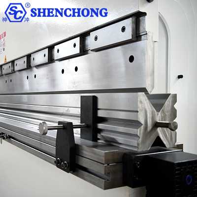
The slider is the core actuator of a CNC press bending machine, and its positioning accuracy directly affects the bending angle and product consistency.
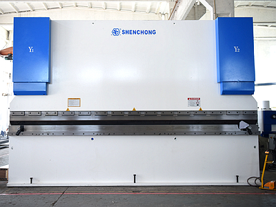
For electro-hydraulic CNC press brake machines, the Y1 and Y2 axes typically control the positions of the hydraulic cylinders on both sides of the slider, respectively.
Main optimization methods include:
- Regularly calibrating the position feedback system of the Y1 and Y2 axes.
- Checking the working status of the grating ruler, servo valve, and hydraulic system.
- Keeping the hydraulic oil clean and controlling the oil temperature.
- Checking the slider guide clearance and mechanical wear.
- Using an appropriate slow bending speed to improve forming stability.
- Regularly verifying slider parallelism and repeatability.
For high-precision bending, equipment with high repeatability should be selected based on workpiece tolerance requirements, rather than simply pursuing the maximum tonnage of the equipment.
During long plate bending, the frame and worktable will undergo elastic deformation due to the bending force.
Without proper compensation, the angles at both ends of the workpiece may be normal, while the angle in the middle may be excessive.
Optimization Recommendation:
- Prioritize the use of CNC mechanical deflection compensation or a suitable hydraulic deflection compensation system.
- Set the compensation based on the material thickness, length, die opening, and actual bending force.
- Use a long plate for trial bending, measuring the angles at the left, middle, and right ends respectively.
- Gradually adjust the compensation curve based on the angle distribution.
- Save the verified compensation data to the corresponding bending program.
Note:
Deflection compensation mainly addresses the angle distribution along the bending length; it cannot replace Y1/Y2 parallelism calibration, nor can it completely eliminate material springback differences.
Springback is one of the main causes of unstable bending angles.
During bending, metal sheets undergo elastoplastic deformation. After unloading, the elastically deformed portion recovers, causing a change in the actual bending angle.
Different materials exhibit different springback characteristics:
Materials | Springback Characteristics | Improvement methods |
Q235 carbon steel | Generally easier to control | Stabilize plate thickness, die, and bending parameters |
304 stainless steel | Springback is usually more pronounced under the same conditions | Increase springback compensation and rationally select inner radius |
5052 aluminum alloy | Significantly affected by material condition | Control bending radius to avoid cracking |
High-strength steel | Bending force and springback may be relatively large | Use dedicated dies and angle compensation |
Galvanized steel sheet | Angle and surface quality must be considered | Control indentation friction with the die |
Methods to improve springback control accuracy include material batch management, trial bending database, angle measurement feedback, and adaptive bending compensation.
The back gauge directly determines the dimensional accuracy of the bent edge.
For multi-process, multi-angle, and complex sheet metal parts, it is recommended to configure the following based on the workpiece structure:
- X-axis: Controls the back gauge's front-to-back position.
- R-axis: Controls the back gauge's vertical position.
- Z1/Z2 axes: Adjust the lateral position of the stop finger.
- X1/X2 axes: Suitable for complex workpieces requiring independent front-to-back positioning.
For complex bent parts, a 6+1 axis or higher configuration provides more flexible positioning capabilities, but whether to increase the number of axes should be determined by the workpiece structure and processing technology.
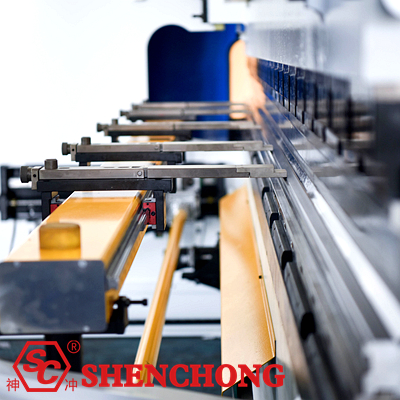
Traditional bending relies on manual trial bending and adjustment, which easily leads to long first-piece debugging times.
Using an online angle detection system can automatically measure and correct angles, provided the equipment supports it.
Basic Process:
Input target angle and material parameters
↓
Execute bending process
↓
Measure actual bending angle
↓
Calculate deviation and correct bending parameters
↓
Verify pass and save process data
Whether the angle closed-loop system can correct the current bending process in real time depends on the functions of the sensors, controllers, and equipment; some systems can only apply corrections in the next piece or the next bend.
Recommended key checks:
- Y1/Y2 axis repeatability accuracy.
- Back gauge X-axis positioning accuracy.
- Upper and lower die center lines and clamping status.
- Worktable straightness.
- Deflection compensation mechanism.
- Graphical ruler, limit switches, and safety protection devices.
Equipment accuracy must be verified through measurement data and cannot be judged solely based on processing experience.
Die is a crucial factor affecting bending accuracy, bending radius, surface quality, and processing efficiency.
For common low-carbon steel air bending processes, the V-groove opening can be initially selected within a range of approximately 6 to 10 times the plate thickness.
V = k·t
Where:
- V: Lower die V-groove width (mm)
- t: Plate thickness (mm)
-k: V-groove selection coefficient, commonly used in the initial selection range of 6 to 10
The following example uses 8 times the plate thickness:
Plate thickness | Initial selection of V-groove | Main considerations |
1 mm | 8 mm | Thin Sheet Forming and Indentation |
2 mm | 16 mm | Conventional Sheet Metal Bending |
3 mm | 24 mm | Bending Force and Inner Radius Balance |
4 mm | 32 mm | Stable Forming |
5 mm | 40 mm | Die Load Capacity |
6 mm | 48 mm | Bending Force and Minimum Edge Length |
8 mm | 64 mm | Thick Plate Forming Capacity |
The above is a preliminary example and not a universally mandatory standard. Actual considerations also include material strength, inner bending radius, minimum bending edge length, die angle, and equipment rated capacity.
For 90° air bending, a simplified estimation formula can be used:
F ≈ (1.42·σb·L·t²) / (1000·V)
Where:
F: Bending force, kN
σb: Material tensile strength, N/mm²
L: Bending length, mm
t: Plate thickness, mm
V: Width of the lower die V-groove, mm
For example: A 3mm thick, 3200mm long low-carbon steel plate, assuming a tensile strength of 450MPa and a V-groove width of 24mm.
F ≈ (1.42 × 450 × 3200 × 32) / (1000 × 24)
The calculated result is approximately:
F ≈ 767kN ≈ 78.2 tons of force
This is an estimate for initial selection of air bending. In practice, the per-meter load capacity of the die, the equipment load curve, off-center load limits, and safety margins should also be checked. The feasibility of processing cannot be determined solely by the total tonnage.
For multi-variety, small-batch production, die changeover time is often a significant factor affecting equipment efficiency.
It is recommended to use standardized segmented dies, quick-clamping systems, and die numbering management to reduce manual adjustment time.
The following can be selected based on material and surface requirements:
- Anti-indentation dies or protective films.
- Suitable rounded corner punches.
- High-quality die surface treatment.
- Dedicated low-friction die structure.
- A reasonable die cleaning and maintenance system.
Especially in the manufacturing of stainless steel decorative panels, elevator panels, and high-end chassis, the surface quality of bending is just as important as angular accuracy.
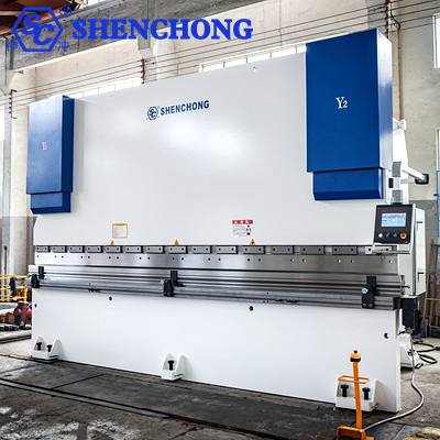
Complex sheet metal parts often require multiple bends.
An unreasonable sequence may cause interference between the workpiece and the slider, mold, back gauge, or frame.
A reasonable bending sequence should comprehensively consider the workpiece structure, bending direction, mold space, positioning reference, and operational convenience.
It is generally recommended to first confirm the process feasibility through 3D bending simulation before determining the final bending sequence. Simply applying "inside before outside" or "short before long" as a uniform rule for all workpieces is not advisable.
Offline programming allows for the preparation of the next batch of workpiece programs in advance while the equipment is processing other orders.
The main benefits include reducing on-site programming time, early interference identification, optimized mold selection, and reduced trial bending times.
For sheet metal companies with a wide variety of orders and frequent line changes, offline programming is usually a priority for improvement.
A complete processing cycle of a CNC press bending machine typically includes rapid approach, deceleration bending, pressure holding or unloading, rapid return, and workpiece repositioning.
While meeting process quality and safety requirements, the approach speed, speed transition position, bending speed, and return stroke can be optimized.
Safety limits should not be arbitrarily increased or protective functions removed simply to shorten cycle time.
Combining orders with similar materials, molds, and processes helps reduce mold changeovers and program switching time.
For multi-variety, small-batch production, the benefits of mold changeover optimization and process standardization are sometimes more significant than increasing the slider speed.
For long plates, thin plates, large-area metal sheets, and heavy workpieces, manual sheet support can easily cause sheet sagging, unstable positioning, and operator fatigue.
A bending follower sheet support system controls the sheet support mechanism to support the sheet along a preset trajectory during the CNC press bending process.
Key advantages include:
- Reducing sagging of large sheet metal due to its own weight.
- Improving workpiece support stability during bending.
- Reducing the labor intensity of manual material handling.
- Reducing the risk of surface scratches on sheet metal.
- Improving the consistency of repeated positioning.
- Improving the ease of handling long plates and large-area sheet metal parts.
Particularly suitable for elevator door panels, cabinet side panels, container panels, air conditioner casings, and architectural metal panels.
It should be noted that the follow-up material handling device mainly improves support and handling conditions and does not directly replace slider accuracy, back gauge positioning, or angle compensation. Material handling capacity still needs to be calculated based on workpiece mass, center of gravity, dimensions, and motion trajectory.
Traditional hydraulic CNC press brake machines typically use a motor-driven hydraulic pump to provide system power.
Hybrid electric servo press brake machines, however, can output flow and pressure as needed through a servo motor and pump control system, depending on the equipment structure and control strategy.
Comparison Items | Traditional hydraulic systems | Hybrid servo system |
Power Control | Commonly use continuously operating pump stations | Can adjust motor output according to operating conditions |
Energy Consumption | High idle and partial load rates | Potential to reduce standby power consumption |
Noise | Affected by continuous pump station operation | Advantages are generally better under low load conditions |
Oil Temperature Control | May require more cooling | May reduce some heat loss |
Dynamic Response | Depends on valve control and pump station configuration | Depends on servo pump and control strategy |
Maintenance Requirements | Routine maintenance of hydraulic systems | Consider both hydraulic and servo drive |
Hybrid systems do not guarantee higher precision or faster cycle times in all operating conditions. Actual improvements should be confirmed through energy consumption, cycle time, and quality testing using the same materials, molds, and bending procedures.
Robotic bending is a crucial technology for improving the capacity of repetitive orders, batch sheet metal manufacturing, and multi-shift production.
Robotic bending systems typically include CNC bending machines, industrial robots, fixtures, material positioning tables, flipping devices, finished product palletizing devices, and safety protection systems.
Key advantages of robotic bending:
- Reduced labor intensity from repetitive handling and flipping.
- Improved consistency of actions for batch orders.
- Supports continuous production and automated loading and unloading.
- Reduces some positioning fluctuations caused by manual operation.
- Facilitates production data recording and quality traceability.
- Integrates with automated warehousing, laser cutting, and production management systems.
Robotic press brake bending is particularly suitable for products with stable batch production, mature CNC press bending processes, and easy workpiece clamping.
For enterprises producing a wide variety of products in small batches, the focus should be on evaluating robot programming time, fixture changeover time, and return on investment in automation, rather than solely basing selection on whether the robot can operate continuously.
Modern CNC systems not only control the movement of bending machines but also help enterprises establish standardized process databases.
For example, using ESA, Delem, CYBELEC, or other CNC systems with corresponding functions allows for varying degrees of graphical programming, material database management, bending sequence management, compensation parameter storage, and equipment status monitoring, depending on the specific model and software options.
For common 4+1 axis and 6+1 axis CNC press brake bending machines, the following functions can be optimized:
CNC Functions | Optimize Value |
Material Database | Reduced repetitive material parameter input |
Die Database | Improved mold selection consistency |
Bending Program Storage | Facilitated quick recall for recurring orders |
Deflection Compensation Management | Improved long plate angle consistency |
Automatic Backgauge Positioning | Reduced manual adjustments |
Graphical Programming | Reduced programming difficulty for complex workpieces |
Angle Compensation | Reduce trial bending and rework |
Production Data Recording | Supported process analysis and traceability |
Specific functions must be based on the equipment controller version, authorized software, and external sensor configuration.
High-quality CNC press bending processing cannot rely solely on equipment precision; a comprehensive quality management process is also necessary.
It is recommended to establish a three-stage quality control mechanism.
- Before processing: Verify the material, plate thickness, mold, program, bending direction, and equipment status. Check for any collision risks with the mold and workpiece.
- During processing: Perform first-piece inspection, record the bending angle, bending edge dimensions, and surface quality, and determine the sampling frequency based on batch stability.
- After processing: Conduct finished product dimensional inspection, visual inspection, and quality record keeping. Analyze the root causes of non-conforming products.
Indicators | Calculation Method | Improvement Goals |
First Article Acceptance Rate | First-piece acceptable batch / Total batches | Reduce setup and trial runs |
First-Pass Acceptance Rate | Number of acceptable pieces at one time / Total number of processed pieces | Reduce rework |
Average Processing Cycle | Total processing time / Number of acceptable pieces | Increase production capacity |
Average Mold Change Time | Total mold change time / Number of mold changes | Reduce auxiliary time |
Overall Equipment Effectiveness (OEE) | Time utilization rate × Performance utilization rate × Quality pass rate | Improve equipment utilization efficiency |
These metrics should be recorded continuously to avoid evaluating equipment performance based solely on a single best processing speed.
Application Industries | Processing Characteristics | Recommended optimization directions |
Electrical cabinets | Multiple bending, small batches, high dimensional requirements | Offline programming, quick clamping, multi-axis back gauge |
Elevator manufacturing | Large area thin plates, high surface quality requirements | Follow-up material support, anti-indentation molds |
Automotive parts | Batch production, high consistency requirements | Robot bending, angle detection |
Building curtain walls | Long plates, large-size plates | Deflection compensation, long plate support |
Stainless steel products | Significant springback, high surface requirements | Springback compensation, specialized molds |
Construction machinery | Thick plates, high-strength materials | Tonnage verification, mold load-bearing capacity |
Air conditioning and ventilation equipment | Processing of thin plates in multiple specifications | Quick mold change, program database |
Metal furniture | Multiple varieties, repeat orders | Standardized processes, flexible production |
1) Improve Equipment Positioning Accuracy: Calibrate the parallelism of Y1/Y2 axes, back gauge, and slide block.
2) Optimize Deflection Compensation: Improve the consistency of bending angles for long plates.
3) Control Material Springback: Establish a database of material parameters and bending compensation.
4) Optimize Die Configuration: Rationally select V-grooves, punches, and quick clamping systems.
5) Optimize Bending Sequence: Reduce interference and workpiece flipping through simulation.
6) Adopt Offline Programming: Reduce on-site programming and equipment waiting time.
7) Introduce Follow-up Material Handling: Improve support and operation efficiency for large workpieces.
8) Upgrade Servo Control: Reduce unnecessary energy consumption.
9) Promote Robotic Bending: Improve production consistency for orders suitable for automation.
10) Establish a Quality Data System: Continuously track pass rate, cycle time, and rework rate.
For sheet metal companies planning to upgrade their production lines, it is recommended to implement the upgrade in three phases.
Phases | Implementation Content | Investment Characteristics |
Phase 1: Basic Improvement | Equipment calibration, mold optimization, standardized operations, process database | Relatively low investment, priority implementation |
Phase 2: Process Upgrade | Offline programming, rapid clamping, follow-up material handling, angle detection | Selective investment based on product structure |
Phase 3: Intelligent Manufacturing | Robot bending, automated loading and unloading, production data integration | Higher investment, return on investment needs to be evaluated |
For companies that already possess CNC bending machines, the most worthwhile priorities are usually equipment precision calibration, mold standardization, bending program optimization, and first-piece quality management. These measures can address the main issues in the existing process first, and then determine whether to introduce follow-up material handling, hybrid electric servo equipment, or robotic bending systems based on capacity requirements.
CNC press bending technology is evolving from single-machine processing to digital, flexible, and automated production.
Future key areas of focus include adaptive angle compensation, digital bending process databases, automatic mold changing, robotic flexible bending, and integration with intelligent sheet metal warehousing and laser cutting production lines.
For sheet metal processing companies, improving CNC press bending processing capabilities should revolve around five goals: higher bending accuracy, more stable product quality, shorter production cycles, lower overall costs, and more flexible production capacity.
Ultimately, companies should choose technological improvement solutions suitable for their own production needs based on sheet thickness, workpiece size, product complexity, order volume, and quality requirements, rather than simply pursuing equipment configuration upgrades.