Sheet metal structural parts are an important part of current host products and construction projects. They are entities with a certain shape and capable of bearing loads. It can be seen from the definition that bearing load is one of its basic properties. Therefore, sheet metal structural parts quality has an important impact on the performance and strength of the entire structure.
According to experience, there are three main factors that affect its performance:
① Raw materials:
Since structural parts mostly use profiles or special-shaped materials, such materials themselves undergo a deformation process during the processing process. There is stress inside the material itself. After being affected by aging such as changes in external temperature, it will deform itself, which may lead to deformation of the overall structure;
② Docking method:
Structural parts are made of multiple profiles or sheet metal parts butted together. Their main force-bearing modes are different, and different docking methods must be adopted. The section coefficient of the material itself is used to improve its load-bearing or deformation resistance.
② Welding deformation:
Traditional welding methods often cause thermal deformation of the finished product, resulting in changes in the performance of the product itself. This requires taking measures to reduce the occurrence of welding thermal deformation.
According to experience, there are three main factors that affect its performance: raw materials, docking methods and welding deformation. The following will be analyzed from the above three aspects.
At present, there are two main processing methods for profiles, which are explained below.
One is to use strip steel to form the required cross-sectional shape after rolling. After that, the required profile is obtained through high-frequency welding.
This forming method refers to uncoiling the raw material (generally referred to as strip steel) and obtaining the required specifications of the profile after roll forming, which is directly formed into a square, rectangular or special-shaped tube.
This forming method is divided into two types. One is that the strip is directly formed into a profile of the required cross-section, that is, it is formed step by step. Second, the strip steel is first formed into a round tube, and then the formed round tube is rolled into a profile of the required cross-section using a rolling die, that is, secondary forming.
The overall process flow of secondary forming is the same as that of pass-by-pass forming, except that a secondary forming process is added after roll shaping. Compared with pass-by-pass forming, although the process level increases, the total number of roll molds required for the same dimensional accuracy is less than that of pass-by-pass forming. Can save part of the mold cost.
But on the other hand, after the strip steel undergoes two plastic deformations of the round tube and the square tube, the internal stress of the final profile will increase.
Compared with step-by-step forming, there may be two sheet metal structural parts quality issues that affect use:
① After the profile is stored for a long time, the internal stress is released, causing the profile to bend and affecting its use.
② Due to the existence of internal stress, deformation of the pipe will release the stress to a certain extent during the later processing process. Eventually, the status of the parts may be inconsistent and different under the same processing parameters.
At the same time, work hardening is common in metal materials. As the degree of cold working deformation increases, the strength and hardness indicators of metal materials increase. However, the plasticity and toughness have decreased. After the strip is deformed twice, the mechanical properties of the material change compared with the step-by-step forming, which will increase the instability and affect the consistency of the final part.
The other is drawing forming, in which the materials used are round tubes with different hole diameters. The required profile is obtained by drawing the mold, and the outer circumference of the material before and after processing is equal. It should be noted that the round tubes used for drawing are also processed using strip roll forming.
Different from pass-by-pass forming and secondary forming, the drawing process refers to a plastic processing method that forces the metal blank to pass through a preset mold under the action of external forces to obtain products consistent with the shape of the mold. The deformation flow of metal during drawing is similar to that of extrusion. However, the change is simpler than that during extrusion, and the unevenness of metal flow is also smaller than during extrusion.
The characteristic of this process is that the outer diameter changes but the total circumference remains unchanged. It should be noted that when the outer diameter changes, the wall thickness will increase or decrease depending on the ratio of the outer diameter to the wall thickness. When the diameter reduction is relatively large, the inner wall of the pipe will become rougher.
Compared with step-by-step forming and secondary forming, the equipment and molds required for the drawing process are relatively simple. Easy to operate and maintain. However, additional surface treatment processes such as pickling, annealing, and aging treatment are required to remove the internal stress generated within the material during processing. And because the deformation caused by the release of internal stress is uncontrollable, it often requires two or multiple drawings to finally obtain the required product. The production efficiency is relatively low and continuous production cannot be achieved. At the same time, due to the existence of the chuck, the end of each profile needs to be removed during drawing, which will produce a certain amount of material waste.
The above are common different processing methods. Although the appearance dimensions of the final profiles are not very different, the internal performance differences are obvious, and they need to be selected according to specific needs.
For example, if it is only used as a support without secondary processing, choosing a drawn profile will not only have high material strength, but also relatively low processing costs. If profiles need to be processed into other shapes later, such as curved beams and other deformed products, it is recommended to choose raw materials processed by roll forming. The final internal stress of the material in this processing method is relatively small, the deformation produced after processing into parts or products is relatively small, and the consistency of the finished product is relatively good.
Various structural parts are often made by butt welding of multiple parts, and the butt method will also affect their final performance. If the docking method is unreasonable, the rigidity of the material itself will not be properly utilized, resulting in a decrease in performance.
The following are examples:
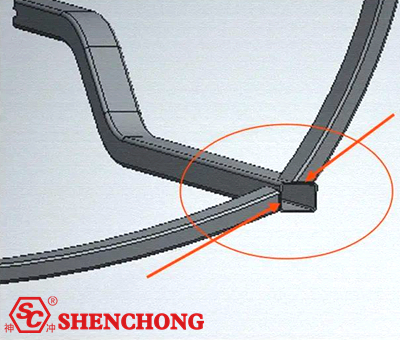
1) Three faces are connected at the corners, and this method is adopted for the frame structure.
If the main force direction is the horizontal plane, such as a factory building, etc., it is recommended to select steel beams in the vertical direction as the support point. The connecting surfaces of the steel beams on both sides are on the steel beams as support points. The two side beams are directly connected to the vertical beams in the horizontal direction. When an external force is applied in the horizontal direction, the force is transmitted through the horizontal beam and acts on the vertical beam. The edge of the vertical beam can be used as a support surface, and the horizontal beam can also play a supporting role. This can make full use of the strength of the material itself and reduce the deformation of the overall structure in the horizontal direction.
Figure 1 The two side beams are directly connected to the vertical beams

2) There are two ways of docking between two vertical beams. For the convenience of explanation, a shaped structure is selected for analysis.
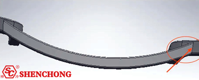
The state shown in Figure 2: the two side beams are directly connected to the vertical beams

A cross beam is used to connect two vertical beams, but the cross beam is on the outside of the two vertical beams. At this time, after receiving force in the horizontal direction, it can only be guaranteed by the strength of the welding seam position. If the weld strength is insufficient, desoldering will occur, and the rigidity of the beam itself cannot provide significant support.
Figure 3 shows another connection method: a cross beam is used to connect two vertical beams

The crossbeam is between two vertical beams. The support point of the cross beam is on the opposite surface of the two vertical beams. At this time, after the overall structure is subjected to horizontal force, the rigidity of the beam itself and the strength of the weld seam can be used as support for the overall structure. Moreover, the rigidity of the beam itself is fully utilized, and the rigidity of the overall structure can be effectively improved.
The connection structure in the vertical direction is similar. Try to make the rigidity of the material itself participate in the rigid support of the overall structure as much as possible, and avoid relying solely on the strength of the weld to ensure the rigidity of the overall structure.
Welding is a thermal process that uses the instantaneous high temperature generated by electric current to melt steel and bond parts together. The joints processed in this way have high strength. However, due to the high temperature, the stress balance inside the material is broken, which will cause the structural parts to deform. And as time continues, deformation will gradually occur until a new equilibrium is reached, and this phenomenon is inevitable.
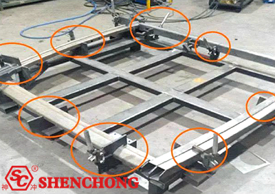
Before welding, make positioning fixtures from materials that are no less rigid than the parts being processed. The spatial position of all parts to be welded is fixed. While achieving accurate position and size of the parts, the position and shape of the parts are fixed through the clamp on the fixture. The rigidity of the fixture itself is used to control the deformation of the parts during the welding process.
As shown in Figure 4: welding after fixation. Use U-shaped fixing blocks, clamps, etc. to fix the parts before welding.

Although the deformation of the product after welding is small in this way, there is a large internal stress inside each component. It will be affected by aging when stored outside or in an open-air environment for a long time, and deformation may occur after a long time.
Similar to the principle of stamping adjustment springback, the structural parts that need to be welded are analyzed, and their deformation direction and degree are predicted in advance based on experience. During the welding process, the parts are welded in the opposite direction of deformation, and the deformation after welding is used to make the structural parts reach the required size.
The disadvantage of this method is that the entire process is controlled based on the operator's experience. Precise control is not possible. Suitable for products that do not have high size requirements or do not require coordinated installation.
Before welding, after determining the position of the parts, spot welding is performed at the joints of the components. The principle is similar to using a fixture. The welding points are used to fix the shape of the part before welding. Use the strength of the solder joint to control the thermal deformation of the sheet metal structural part. This method requires advance ordering. The workload is heavy.
During the welding process, the deformation caused by each weld generally cannot offset each other. The final deformation direction is always consistent with the deformation direction caused by the first weld. Using this phenomenon, the welding sequence can be determined to reduce welding deformation.
This article explains the production and processing of sheet metal structural parts from three aspects: raw materials, component docking methods and post-weld deformation solutions.
Through the analysis of this article, it can be known that the selection of raw materials should be based on the final use environment. Reasonable component docking methods can play an important role in affecting the performance of steel structures. Reasonable docking methods can improve the overall rigidity of the structural parts themselves. Welding deformation cannot be effectively avoided at present. However, by making fixtures and optimizing the welding process, welding deformation can be reduced and the impact on performance quality can be reduced, thereby ensuring the stability of the sheet metal structural parts quality.